Brother International ZE-856A Instruction Manual - English and Spanish - Page 176
Adjusting the synchronizer, 10. Einstellen des Synchronisators, 10. R, glage du synchroniseur,
 |
View all Brother International ZE-856A manuals
Add to My Manuals
Save this manual to your list of manuals |
Page 176 highlights
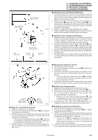
13. STANDARD ADJUSTMENTS 13. STANDARDEINSTELLUNGEN 13. REGLAGES STANDARD 13. AJUSTES ESTANDARES 13-10. Adjusting the synchronizer 13-10. Einstellen des Synchronisators 13-10. Réglage du synchroniseur 13-10. Ajuste del sincronizador Needle up stop Nadelstopposition, oben Position d'arrêt supérieure de I'aiguille Parada con la aguja arriba 1021S Needle down stop Nadelstopposition, unten Position d'arrêt inférieure de I'aiguille Parada con la aguja abajo 1022S 1023S Direction of machine pulley rotation Riemenscheibendrehrichtung Sens de rotation de la poulie de machine Dirección de rotación de la polea de la máquina q 0.5mm 0,5mm U 2 D -2.5 1 1024S 1025S 1026S • The synchronizer consists of two elements which are used to detect the needle position. One of these elements is used to control the needle down signal and the thread trimmer signal. • When the power is turned on and the sewing machine stops in the needle up stop position, the reference line on the thread take-up lever should stop near the U mark on the face plate (± 3 mm). Furthermore, when the sewing machine stops in the needle down stop position, the reference line on the thread take-up lever should stop near the D mark on the face plate (± 4 mm). I Needle up stop position adjustment 1. Turn off the power switch. 2. Loosen the two set screws q. 3. Move set screw q in the direction of normal puley rotation to raise the needle bar w. Move the screw q in the opposite direction to lower the needle bar. 4. Tighten the set screws q. I Needle down and thread trimmer signals Do not adjust the needle down stop position. I Note • The synchronizer is preadjusted at the factory. Do not remove the synchronizer after removing the pulley. • When mounting the pulley be sure to leave a 0.5 mm gap between the pulley edge and synchronizer. Furthermore, tighten the two machine pulley set screws so that the rear set screw is at the screw stop on the upper shaft when seen from the machine pulley turning direction. 157 ZE-855A,856A
-
 1
1 -
2
-
3
-
4
-
5
-
6
-
7
-
8
-
9
-
10
-
11
-
12
-
13
-
14
-
15
-
16
-
17
-
18
-
19
-
20
-
21
-
22
-
23
-
24
-
25
-
26
-
27
-
28
-
29
-
30
-
31
-
32
-
33
-
34
-
35
-
36
-
37
-
38
-
39
-
40
-
41
-
42
-
43
-
44
-
45
-
46
-
47
-
48
-
49
-
50
-
51
-
52
-
53
-
54
-
55
-
56
-
57
-
58
-
59
-
60
-
61
-
62
-
63
-
64
-
65
-
66
-
67
-
68
-
69
-
70
-
71
-
72
-
73
-
74
-
75
-
76
-
77
-
78
-
79
-
80
-
81
-
82
-
83
-
84
-
85
-
86
-
87
-
88
-
89
-
90
-
91
-
92
-
93
-
94
-
95
-
96
-
97
-
98
-
99
-
100
-
101
-
102
-
103
-
104
-
105
-
106
-
107
-
108
-
109
-
110
-
111
-
112
-
113
-
114
-
115
-
116
-
117
-
118
-
119
-
120
-
121
-
122
-
123
-
124
-
125
-
126
-
127
-
128
-
129
-
130
-
131
-
132
-
133
-
134
-
135
-
136
-
137
-
138
-
139
-
140
-
141
-
142
-
143
-
144
-
145
-
146
-
147
-
148
-
149
-
150
-
151
-
152
-
153
-
154
-
155
-
156
-
157
-
158
-
159
-
160
-
161
-
162
-
163
-
164
-
165
-
166
-
167
-
168
-
169
-
170
-
 171
171 -
 172
172 -
 173
173 -
 174
174 -
 175
175 -
 176
176 -
 177
177 -
 178
178 -
 179
179 -
 180
180 -
 181
181 -
182
-
183
-
184
-
185
-
186
-
187
-
188
-
189
-
190
-
191
-
192
-
193
-
194
-
195
-
196
-
197
-
198
-
199
-
200
-
201
-
202
-
203
-
204
-
205
-
206
-
207
-
208
-
209
-
210
-
211
-
212
-
213
-
214
-
215
-
216
-
217
-
218
-
219
-
220
-
221
-
222
-
223
-
224
-
225
-
226
-
227
-
228
-
229
-
230
-
231
-
232
-
233
-
234
-
235
-
236
-
237
-
238
-
239
-
240
-
241
-
242
-
243
-
244
-
245
-
246
-
247
-
248
 |
 |
