Brother International ZE-856A Instruction Manual - English and Spanish - Page 180
Adjusting the thread trailing length after thread trimming 856A only
 |
View all Brother International ZE-856A manuals
Add to My Manuals
Save this manual to your list of manuals |
Page 180 highlights
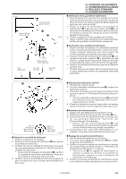
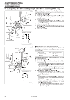
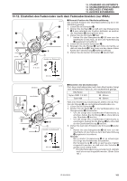
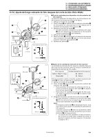
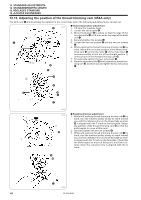
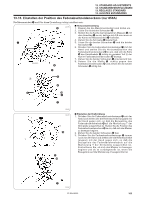
13. STANDARD ADJUSTMENTS 13. STANDARDEINSTELLUNGEN 13. REGLAGES STANDARD 13. AJUSTES ESTANDARES 13-12. Adjusting the thread trailing length after thread trimming (856A only) e r 5 mm r 5 mm e 1032S w y q t 2 - 4 mm B A Seen from direction B A t e I Standard position for upper thread feeding device The standard position for the upper thread feeding device is as shown in the illustration. 1. Loosen the set screw q. 2. Turn the base w so that the end of the wire e is at a position 5 mm below the position where the upper thread r passes. 3. Tighten the set screw q. * At this time, keep the end of the wire e 0.5 mm away from surface A of the part where the thread guide t is installed. 4. Loosen the two bolts y. 5. Move the wire e to the left or right so that the end of the wire e is 2 to 4 mm from the top-left edge of the thread guide t. 6. Tighten the bolts y. 0.5 mm 1033S Stronger Weaker r e Should not touch u e Longer r Shorter 1034S y w q t B A Seen from direction B A t e 0.5 mm 1033S I Adjusting the upper thread trailing amount The standard upper thread trailing amount after thread trimming varies as shown below depending on the type of thread used. Upper thread Upper thread trailing amount nylon 100D 1 X 3(Z) 50 - 60mm #60 spun 40 - 50mm If adjustment is necessary, adjust the position of the wire e as described below. 1. Loosen the set screw q. 2. Turn the base w to adjust the vertical position of the end of the wire e. • To increase the upper thread trailing amount, raise the position of the wire e without letting it touch the upper thread r. • To decrease the upper thread trailing amount, lower the position of the wire e without letting it touch the thread guide t. 3. After adjusting, tighten the set screw q. * At this time, keep the end of the wire e 0.5 mm away from surface A of the part where the thread guide t is installed. Note: If the tension of the pre-tension y is to strong, it will be more difficult to adjust the upper thread trail- ing amount. The pre-tension y should be adjusted to as weak a tension as possible while still allowing the rotary disc u to rotate smoothly. * The thread tension will change at this time, so be sure to re-adjust the upper thread tension. (Refer to page 131.) 161 ZE-855A,856A
-
 1
1 -
2
-
3
-
4
-
5
-
6
-
7
-
8
-
9
-
10
-
11
-
12
-
13
-
14
-
15
-
16
-
17
-
18
-
19
-
20
-
21
-
22
-
23
-
24
-
25
-
26
-
27
-
28
-
29
-
30
-
31
-
32
-
33
-
34
-
35
-
36
-
37
-
38
-
39
-
40
-
41
-
42
-
43
-
44
-
45
-
46
-
47
-
48
-
49
-
50
-
51
-
52
-
53
-
54
-
55
-
56
-
57
-
58
-
59
-
60
-
61
-
62
-
63
-
64
-
65
-
66
-
67
-
68
-
69
-
70
-
71
-
72
-
73
-
74
-
75
-
76
-
77
-
78
-
79
-
80
-
81
-
82
-
83
-
84
-
85
-
86
-
87
-
88
-
89
-
90
-
91
-
92
-
93
-
94
-
95
-
96
-
97
-
98
-
99
-
100
-
101
-
102
-
103
-
104
-
105
-
106
-
107
-
108
-
109
-
110
-
111
-
112
-
113
-
114
-
115
-
116
-
117
-
118
-
119
-
120
-
121
-
122
-
123
-
124
-
125
-
126
-
127
-
128
-
129
-
130
-
131
-
132
-
133
-
134
-
135
-
136
-
137
-
138
-
139
-
140
-
141
-
142
-
143
-
144
-
145
-
146
-
147
-
148
-
149
-
150
-
151
-
152
-
153
-
154
-
155
-
156
-
157
-
158
-
159
-
160
-
161
-
162
-
163
-
164
-
165
-
166
-
167
-
168
-
169
-
170
-
171
-
172
-
173
-
174
-
 175
175 -
 176
176 -
 177
177 -
 178
178 -
 179
179 -
 180
180 -
 181
181 -
 182
182 -
 183
183 -
 184
184 -
 185
185 -
186
-
187
-
188
-
189
-
190
-
191
-
192
-
193
-
194
-
195
-
196
-
197
-
198
-
199
-
200
-
201
-
202
-
203
-
204
-
205
-
206
-
207
-
208
-
209
-
210
-
211
-
212
-
213
-
214
-
215
-
216
-
217
-
218
-
219
-
220
-
221
-
222
-
223
-
224
-
225
-
226
-
227
-
228
-
229
-
230
-
231
-
232
-
233
-
234
-
235
-
236
-
237
-
238
-
239
-
240
-
241
-
242
-
243
-
244
-
245
-
246
-
247
-
248
 |
 |
