Brother International ZE-856A Instruction Manual - English and Spanish - Page 191
Ze-855a,856a, Dipsw1, Dipsw2
 |
View all Brother International ZE-856A manuals
Add to My Manuals
Save this manual to your list of manuals |
Page 191 highlights
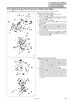
DIPSW1 DIPSW2 q 13. STANDARD ADJUSTMENTS 13. STANDARDEINSTELLUNGEN 13. REGLAGES STANDARD 13. AJUSTES ESTANDARES Accurately set the DIP switches, otherwise abnormal operation may result. 1. Remove the six screws q and then open the control box cover w. Note: When opening the cover w, hold it securely so that it does not fall down. 2. Set DIP switches. Refer to the table on page 173 for details of the DIP switch functions. 3. Close the cover w and tighten the screw q. Die DIP-Schalter genau einstellen, da es sonst zu Fehlbetrieb kommen kann. 1. Entfernen Sie die sechs Schrauben q und öffnen Sie die Schaltkastenabdeckung w. Hinweis: Halten Sie die Abdeckung w beim Öffnen fest, so daß sie nicht herunterfallen kann. 2. Stellen Sie die DIP-Schalter. Für weitere Einzelheiten zu den DIP-Schalterfunktionen wird auf die Tabelle auf Seite 174 verwiesen. 3. Die Abdeckung w schließen und die Sehraube q festziehen. w 1394M Régler précisément les interrupteurs DIP, sinon la machine risquera de fonctionner anormalement. 1. Retirer les six vis q puis ouvrir le couvercle w du boîtier de commande. Remarque: Lorsqu'on ouvre le couvercle w, le tenir fermement afin qu'il ne tombe pas. 2. Régler les interrupteurs DIP. Pour plus de détails concernant les fonctions des interrupteurs DIP, se reporter au tableau de la page 175. 3. Refermer le couvercle w et resserrer la vis q. Ajustar correctamente los interruptores DIP porque, de lo contrario, puede funcionar mal. 1. Quitar los seis tornillos q y luego abrir la cubierta de la caja de controles w. Nota: Al abrir la cubierta w, sostenerla bien de manera que no se caiga. 2. Ajustar los interruptores DIP. Consultar el cuadro en la página 176 para más detalles sobre las funciones de los interruptores DIP. 3. Cerrar la tapa w y apretar el tornillo q. ZE-855A,856A 172
-
 1
1 -
2
-
3
-
4
-
5
-
6
-
7
-
8
-
9
-
10
-
11
-
12
-
13
-
14
-
15
-
16
-
17
-
18
-
19
-
20
-
21
-
22
-
23
-
24
-
25
-
26
-
27
-
28
-
29
-
30
-
31
-
32
-
33
-
34
-
35
-
36
-
37
-
38
-
39
-
40
-
41
-
42
-
43
-
44
-
45
-
46
-
47
-
48
-
49
-
50
-
51
-
52
-
53
-
54
-
55
-
56
-
57
-
58
-
59
-
60
-
61
-
62
-
63
-
64
-
65
-
66
-
67
-
68
-
69
-
70
-
71
-
72
-
73
-
74
-
75
-
76
-
77
-
78
-
79
-
80
-
81
-
82
-
83
-
84
-
85
-
86
-
87
-
88
-
89
-
90
-
91
-
92
-
93
-
94
-
95
-
96
-
97
-
98
-
99
-
100
-
101
-
102
-
103
-
104
-
105
-
106
-
107
-
108
-
109
-
110
-
111
-
112
-
113
-
114
-
115
-
116
-
117
-
118
-
119
-
120
-
121
-
122
-
123
-
124
-
125
-
126
-
127
-
128
-
129
-
130
-
131
-
132
-
133
-
134
-
135
-
136
-
137
-
138
-
139
-
140
-
141
-
142
-
143
-
144
-
145
-
146
-
147
-
148
-
149
-
150
-
151
-
152
-
153
-
154
-
155
-
156
-
157
-
158
-
159
-
160
-
161
-
162
-
163
-
164
-
165
-
166
-
167
-
168
-
169
-
170
-
171
-
172
-
173
-
174
-
175
-
176
-
177
-
178
-
179
-
180
-
181
-
182
-
183
-
184
-
185
-
 186
186 -
 187
187 -
 188
188 -
 189
189 -
 190
190 -
 191
191 -
 192
192 -
 193
193 -
 194
194 -
 195
195 -
 196
196 -
197
-
198
-
199
-
200
-
201
-
202
-
203
-
204
-
205
-
206
-
207
-
208
-
209
-
210
-
211
-
212
-
213
-
214
-
215
-
216
-
217
-
218
-
219
-
220
-
221
-
222
-
223
-
224
-
225
-
226
-
227
-
228
-
229
-
230
-
231
-
232
-
233
-
234
-
235
-
236
-
237
-
238
-
239
-
240
-
241
-
242
-
243
-
244
-
245
-
246
-
247
-
248
 |
 |
