Brother International PS-300B Instruction Manual - English - Page 117
Making design elements snap to the specified target
 |
View all Brother International PS-300B manuals
Add to My Manuals
Save this manual to your list of manuals |
Page 117 highlights
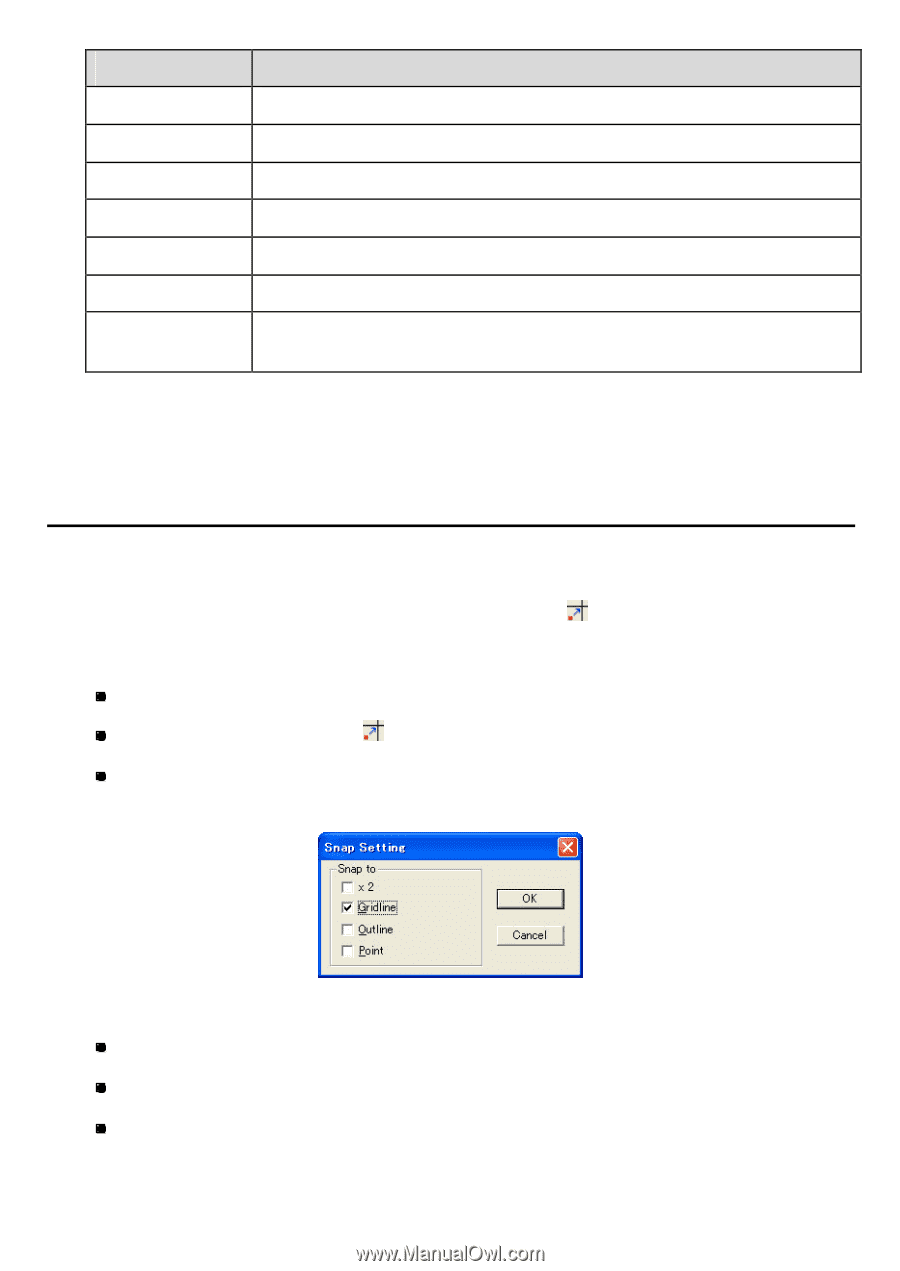
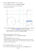
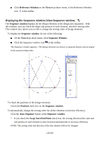
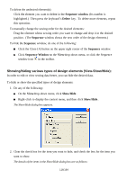
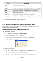
Item Image Outlines Stitches Feeds Codes Connections Sewing Area Explanation Set to show or hide the image. Set to show or hide all outlines. When hidden, outlines cannot be selected. Set to show or hide all stitches. When hidden, stitches cannot be selected. Set to show or hide all feeds. When hidden, feeds cannot be selected. Set to show or hide all codes. Set to show or hide all connection data (feeds or stitches). Set to show or hide the frame of the sewing area when the sewing area of a specified machine model is displayed in the design area. 3. Click the OK button to apply the specified settings. 3-3-4. Making design elements snap to the specified target When creating or editing design elements, they can be aligned on (snapped to) the gridlines, outlines or points for greater precision. To specify the snap setting (View-Snap Setting, ): 1. Do any of the following: On the Viewdrop-down menu, click Snap Setting. Click the Snap Setting icon in the toolbar. Right-click to display the context menu, and then click Snap Setting. The Snap Setting dialog box appears. 2. Do any of the following: To snap to the intersections of the gridlines, check the Gridline check box. To snap to the outlines, check the Outline check box. To snap to points of outline, stitch or feed data, check the Point check box. 117/164
-
 1
1 -
2
-
3
-
4
-
5
-
6
-
7
-
8
-
9
-
10
-
11
-
12
-
13
-
14
-
15
-
16
-
17
-
18
-
19
-
20
-
21
-
22
-
23
-
24
-
25
-
26
-
27
-
28
-
29
-
30
-
31
-
32
-
33
-
34
-
35
-
36
-
37
-
38
-
39
-
40
-
41
-
42
-
43
-
44
-
45
-
46
-
47
-
48
-
49
-
50
-
51
-
52
-
53
-
54
-
55
-
56
-
57
-
58
-
59
-
60
-
61
-
62
-
63
-
64
-
65
-
66
-
67
-
68
-
69
-
70
-
71
-
72
-
73
-
74
-
75
-
76
-
77
-
78
-
79
-
80
-
81
-
82
-
83
-
84
-
85
-
86
-
87
-
88
-
89
-
90
-
91
-
92
-
93
-
94
-
95
-
96
-
97
-
98
-
99
-
100
-
101
-
102
-
103
-
104
-
105
-
106
-
107
-
108
-
109
-
110
-
111
-
 112
112 -
 113
113 -
 114
114 -
 115
115 -
 116
116 -
 117
117 -
 118
118 -
 119
119 -
 120
120 -
 121
121 -
 122
122 -
123
-
124
-
125
-
126
-
127
-
128
-
129
-
130
-
131
-
132
-
133
-
134
-
135
-
136
-
137
-
138
-
139
-
140
-
141
-
142
-
143
-
144
-
145
-
146
-
147
-
148
-
149
-
150
-
151
-
152
-
153
-
154
-
155
-
156
-
157
-
158
-
159
-
160
-
161
-
162
-
163
-
164
 |
 |