Brother International PS-300B Instruction Manual - English - Page 132
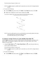
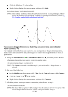
To connect design elements so that they are joined at a point Modify, Point-Connect, Split, Connect
 |
View all Brother International PS-300B manuals
Add to My Manuals
Save this manual to your list of manuals |
Page 132 highlights
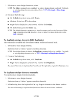
Click the Split icon in the toolbar. Right-click to display the context menu, and then click Split. Each design element can be moved separately. NOTE: After splitting stitch data, stitches should be inserted to form securing stitching in order to prevent the stitching from unraveling. For details on inserting manual stitches, refer to "32-3. Creating manual stitch and manual feed data". To connect design elements so that they are joined at a point (ModifyPoint-Connect, ): The Connect command allows you to join two end (start) points of design elements (outline, manual stitch and manual feed data) allowing you to connect two design elements or close an open outline. 1. Using the Select Point tool or Select Punch Point tool , select the point at the end of a design element that you want to connect to another point. The selected point changes to a black circle . NOTE: The Connect command is available only if a point at the end of a design element is selected. 2. Do one of the following: On the Modify drop-down menu, click Point. On the Point sub- menu, click Connect. Click the Connect icon in the toolbar. Right-click to display the context menu, and then click Connect. 3. Click the point to which you want to connect the point selected in step 1. The two points are connected. NOTE: The shape of mouse pointer will be changed when the pointer is moved over a point at the end of a design element which can connect to the point selected in step 3. 132/164
-
 1
1 -
2
-
3
-
4
-
5
-
6
-
7
-
8
-
9
-
10
-
11
-
12
-
13
-
14
-
15
-
16
-
17
-
18
-
19
-
20
-
21
-
22
-
23
-
24
-
25
-
26
-
27
-
28
-
29
-
30
-
31
-
32
-
33
-
34
-
35
-
36
-
37
-
38
-
39
-
40
-
41
-
42
-
43
-
44
-
45
-
46
-
47
-
48
-
49
-
50
-
51
-
52
-
53
-
54
-
55
-
56
-
57
-
58
-
59
-
60
-
61
-
62
-
63
-
64
-
65
-
66
-
67
-
68
-
69
-
70
-
71
-
72
-
73
-
74
-
75
-
76
-
77
-
78
-
79
-
80
-
81
-
82
-
83
-
84
-
85
-
86
-
87
-
88
-
89
-
90
-
91
-
92
-
93
-
94
-
95
-
96
-
97
-
98
-
99
-
100
-
101
-
102
-
103
-
104
-
105
-
106
-
107
-
108
-
109
-
110
-
111
-
112
-
113
-
114
-
115
-
116
-
117
-
118
-
119
-
120
-
121
-
122
-
123
-
124
-
125
-
126
-
 127
127 -
 128
128 -
 129
129 -
 130
130 -
 131
131 -
 132
132 -
 133
133 -
 134
134 -
 135
135 -
 136
136 -
 137
137 -
138
-
139
-
140
-
141
-
142
-
143
-
144
-
145
-
146
-
147
-
148
-
149
-
150
-
151
-
152
-
153
-
154
-
155
-
156
-
157
-
158
-
159
-
160
-
161
-
162
-
163
-
164
 |
 |
