Brother International PS-300B Instruction Manual - English - Page 126
To delete design elements from the design area Edit-Delete, Delete, Insert
 |
View all Brother International PS-300B manuals
Add to My Manuals
Save this manual to your list of manuals |
Page 126 highlights
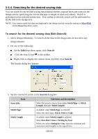
1. Select design element in front of which you want to insert the design elements that have been cut or copied. 2. Do one of the following: On the Edit drop-down menu, click Insert. On the keyboard, press the Insert key. Right-click to display the context menu, and then click Insert. NOTE: If no design element has recently been stored in memory, the Insert command will not be available. Follow the instructions below to place the design element(s) correctly: 1. If the sewing area of a specified machine model is set in the design area: While holding down the keyboard's Shift key, click the left mouse button. The center of the design element (s) aligns with the center of the sewing area. While holding down the keyboard's Ctrl key, click the left mouse button. The center of the design element (s) aligns with the original point of the specified machine model. 2. If the sewing area of a specified machine model is not set in the design area: While holding down the keyboard's Ctrl or Shift key, click the left mouse button. The center of the design element (s) aligns with the origin (0) of the design area's coordinates. * For details on setting a sewing area of a specified machine, refer to "3-7-5. Specifying a sewing machine model". 3. Click a numeric key on the keyboard to display the Input Point dialog box. Then you can input the absolute coordinates of the design element 's center point, then click the OK button. The center of the design element(s) will be placed to the specified point. 4. While holding down the keyboard's Ctrl and Shift key, click the left mouse button. The center of the design element (s) aligns with the center of the design element(s) in the design area. To delete design elements from the design area (Edit-Delete, , Delete): With this command, the following design elements and points can be removed from the design area: Outline data, manual stitch data, manual feed data, images, stitch points and outline's punch points. 126/164
-
 1
1 -
2
-
3
-
4
-
5
-
6
-
7
-
8
-
9
-
10
-
11
-
12
-
13
-
14
-
15
-
16
-
17
-
18
-
19
-
20
-
21
-
22
-
23
-
24
-
25
-
26
-
27
-
28
-
29
-
30
-
31
-
32
-
33
-
34
-
35
-
36
-
37
-
38
-
39
-
40
-
41
-
42
-
43
-
44
-
45
-
46
-
47
-
48
-
49
-
50
-
51
-
52
-
53
-
54
-
55
-
56
-
57
-
58
-
59
-
60
-
61
-
62
-
63
-
64
-
65
-
66
-
67
-
68
-
69
-
70
-
71
-
72
-
73
-
74
-
75
-
76
-
77
-
78
-
79
-
80
-
81
-
82
-
83
-
84
-
85
-
86
-
87
-
88
-
89
-
90
-
91
-
92
-
93
-
94
-
95
-
96
-
97
-
98
-
99
-
100
-
101
-
102
-
103
-
104
-
105
-
106
-
107
-
108
-
109
-
110
-
111
-
112
-
113
-
114
-
115
-
116
-
117
-
118
-
119
-
120
-
 121
121 -
 122
122 -
 123
123 -
 124
124 -
 125
125 -
 126
126 -
 127
127 -
 128
128 -
 129
129 -
 130
130 -
 131
131 -
132
-
133
-
134
-
135
-
136
-
137
-
138
-
139
-
140
-
141
-
142
-
143
-
144
-
145
-
146
-
147
-
148
-
149
-
150
-
151
-
152
-
153
-
154
-
155
-
156
-
157
-
158
-
159
-
160
-
161
-
162
-
163
-
164
 |
 |