Brother International PS-300B Instruction Manual - English - Page 50
Importing an image, Refere nce Point, Shift, Import From File, Image, Look
 |
View all Brother International PS-300B manuals
Add to My Manuals
Save this manual to your list of manuals |
Page 50 highlights
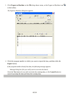
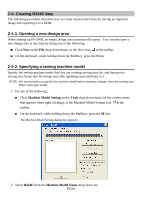
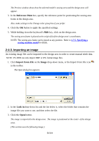
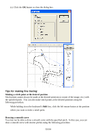
The Preview window shows how the selected model's sewing area and the design area will appear. 3. In the Refere nce Point box, specify the reference point for positioning the sewing area frame in the design area. Also, make settings in the Change color group box if you prefer. 4. Click the OK button to apply the specified settings. 5. While holding down the keyboard's Shift key, click on the design area. The sewing area frame is placed at the origin (0) of the design area's coordinates. NOTE: The sewing area frame can be placed at any position. Refer to 3-7-5. Specifying a sewing machine model for details. 2-4-3. Importing an image An existing image file can be imported to the design area in order to create manual stitch data. NOTE: PS-300B can only import BMP or JPG format image files. 1. Click Import From File on the Image drop-down menu, or the Import From File icon in the toolbar. The Open dialog box appears. 2. In the Look in drop-down list and the list below it, select the folder that contains the image file you want to use, and then select the file. 3. Click the Open button. The image is imported to the design area. The image is positioned at the center of the design area. (This section uses the following image.) 50/164
-
 1
1 -
2
-
3
-
4
-
5
-
6
-
7
-
8
-
9
-
10
-
11
-
12
-
13
-
14
-
15
-
16
-
17
-
18
-
19
-
20
-
21
-
22
-
23
-
24
-
25
-
26
-
27
-
28
-
29
-
30
-
31
-
32
-
33
-
34
-
35
-
36
-
37
-
38
-
39
-
40
-
41
-
42
-
43
-
44
-
 45
45 -
 46
46 -
 47
47 -
 48
48 -
 49
49 -
 50
50 -
 51
51 -
 52
52 -
 53
53 -
 54
54 -
 55
55 -
56
-
57
-
58
-
59
-
60
-
61
-
62
-
63
-
64
-
65
-
66
-
67
-
68
-
69
-
70
-
71
-
72
-
73
-
74
-
75
-
76
-
77
-
78
-
79
-
80
-
81
-
82
-
83
-
84
-
85
-
86
-
87
-
88
-
89
-
90
-
91
-
92
-
93
-
94
-
95
-
96
-
97
-
98
-
99
-
100
-
101
-
102
-
103
-
104
-
105
-
106
-
107
-
108
-
109
-
110
-
111
-
112
-
113
-
114
-
115
-
116
-
117
-
118
-
119
-
120
-
121
-
122
-
123
-
124
-
125
-
126
-
127
-
128
-
129
-
130
-
131
-
132
-
133
-
134
-
135
-
136
-
137
-
138
-
139
-
140
-
141
-
142
-
143
-
144
-
145
-
146
-
147
-
148
-
149
-
150
-
151
-
152
-
153
-
154
-
155
-
156
-
157
-
158
-
159
-
160
-
161
-
162
-
163
-
164
 |
 |