Brother International PS-300B Instruction Manual - English - Page 37
Exporting the data to a sewing machine, BAS311F, Machine Model Name, Reference Point, Shift
 |
View all Brother International PS-300B manuals
Add to My Manuals
Save this manual to your list of manuals |
Page 37 highlights
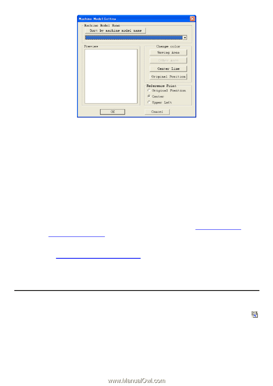
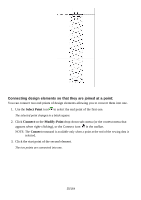
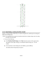
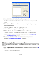
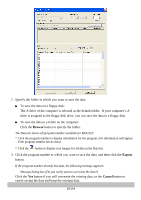
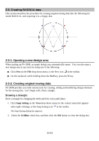
2. Select BAS311F from the Machine Model Name drop-down list. The Preview window shows how the selected model's sewing area and the design area will appear. 3. In the Reference Point box, specify the reference point for positioning the sewing area frame in the design area. Also, make settings in the Change color group box if you prefer. 4. Click the OK button to apply the specified settings. 5. While holding down the keyboard's Shift key, click on the design area. The sewing area frame is placed at the center of the data created in the above procedure. NOTE: The sewing area frame can be placed at any position. Refer to 3-7-5. Specifying a sewing machine model for details. 6. If necessary, adjust the size of the data according to the sewing area frame. (Refer to "3-5-3. Resizing design elements" for details.) 2-2-4. Exporting the data to a sewing machine You can save the data you have created to a storage media (a floppy disk etc.) or a folder on the computer. 1. Click Export to Machine on the File drop-down menu, or the Export to Machine icon in the toolbar. The Export to Machine dialog box appears. 37/164
-
 1
1 -
2
-
3
-
4
-
5
-
6
-
7
-
8
-
9
-
10
-
11
-
12
-
13
-
14
-
15
-
16
-
17
-
18
-
19
-
20
-
21
-
22
-
23
-
24
-
25
-
26
-
27
-
28
-
29
-
30
-
31
-
 32
32 -
 33
33 -
 34
34 -
 35
35 -
 36
36 -
 37
37 -
 38
38 -
 39
39 -
 40
40 -
 41
41 -
 42
42 -
43
-
44
-
45
-
46
-
47
-
48
-
49
-
50
-
51
-
52
-
53
-
54
-
55
-
56
-
57
-
58
-
59
-
60
-
61
-
62
-
63
-
64
-
65
-
66
-
67
-
68
-
69
-
70
-
71
-
72
-
73
-
74
-
75
-
76
-
77
-
78
-
79
-
80
-
81
-
82
-
83
-
84
-
85
-
86
-
87
-
88
-
89
-
90
-
91
-
92
-
93
-
94
-
95
-
96
-
97
-
98
-
99
-
100
-
101
-
102
-
103
-
104
-
105
-
106
-
107
-
108
-
109
-
110
-
111
-
112
-
113
-
114
-
115
-
116
-
117
-
118
-
119
-
120
-
121
-
122
-
123
-
124
-
125
-
126
-
127
-
128
-
129
-
130
-
131
-
132
-
133
-
134
-
135
-
136
-
137
-
138
-
139
-
140
-
141
-
142
-
143
-
144
-
145
-
146
-
147
-
148
-
149
-
150
-
151
-
152
-
153
-
154
-
155
-
156
-
157
-
158
-
159
-
160
-
161
-
162
-
163
-
164
 |
 |