Brother International PS-300B Instruction Manual - English - Page 99
Drawing manual stitch data by tracing an image (Shape-Trace
 |
View all Brother International PS-300B manuals
Add to My Manuals
Save this manual to your list of manuals |
Page 99 highlights
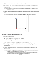
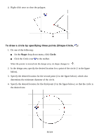
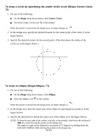
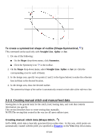
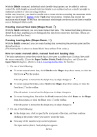
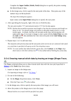
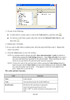
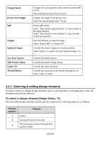
Complete the Input Outline (Stitch, Feed) dialog box to specify the points creating the desired shape of data. In the design area, click to specify the start point of the data. Then press any of the numeric keys on the keyboard. The Input Point dialog box appears. Input values in the Input Point dialog box to specify the next point. 3. After specifying the last point, right-click once to finish the data. The start point marker ("S") and end point marker ("E") for the data appear. NOTE: Stitches that exceed the maximum stitch length or less than the minimum stitch length are shown in red. You should change such stitches in allowable length of pitch, or create stitches again. As default, feed data will not make needle drop, and basting data will make needle drop. If you want to change it, select a point with the Select Point tool, click the Code icon , then add/delete the Trim code on the point in the Code Setting dialog box that appears. 4. Repeat steps 1 to 3 to add more data. The end point of the previous data and the start point of the current one are connected with a feed or a stitch that is specified in Property on the View drop-down menu. NOTE: To create another data linked with the current data, click Continue on the Shape dropdown menu or click the Continue icon in the toolbar before finishing the current data. 3-2-4. Drawing manual stitch data by tracing an image (Shape-Trace, ) The Trace command allows you to draw manual stitch data with the trace pitch specified in Option on the Tools drop-down menu. 1. Import an image to the design area. For importing an image, refer to "3-8. Image." 2. Do one of the following: On the Shape drop-down menu, click Trace. Click the Trace icon in the toolbar. 3. In the design area, click to specify the start point of the image you will trace. 4. Move the pointer in the design area to trace the image. Manual stitches are created with the specified trace pitch. 99/164
-
 1
1 -
2
-
3
-
4
-
5
-
6
-
7
-
8
-
9
-
10
-
11
-
12
-
13
-
14
-
15
-
16
-
17
-
18
-
19
-
20
-
21
-
22
-
23
-
24
-
25
-
26
-
27
-
28
-
29
-
30
-
31
-
32
-
33
-
34
-
35
-
36
-
37
-
38
-
39
-
40
-
41
-
42
-
43
-
44
-
45
-
46
-
47
-
48
-
49
-
50
-
51
-
52
-
53
-
54
-
55
-
56
-
57
-
58
-
59
-
60
-
61
-
62
-
63
-
64
-
65
-
66
-
67
-
68
-
69
-
70
-
71
-
72
-
73
-
74
-
75
-
76
-
77
-
78
-
79
-
80
-
81
-
82
-
83
-
84
-
85
-
86
-
87
-
88
-
89
-
90
-
91
-
92
-
93
-
 94
94 -
 95
95 -
 96
96 -
 97
97 -
 98
98 -
 99
99 -
 100
100 -
 101
101 -
 102
102 -
 103
103 -
 104
104 -
105
-
106
-
107
-
108
-
109
-
110
-
111
-
112
-
113
-
114
-
115
-
116
-
117
-
118
-
119
-
120
-
121
-
122
-
123
-
124
-
125
-
126
-
127
-
128
-
129
-
130
-
131
-
132
-
133
-
134
-
135
-
136
-
137
-
138
-
139
-
140
-
141
-
142
-
143
-
144
-
145
-
146
-
147
-
148
-
149
-
150
-
151
-
152
-
153
-
154
-
155
-
156
-
157
-
158
-
159
-
160
-
161
-
162
-
163
-
164
 |
 |
