Brother International PS-300B Instruction Manual - English - Page 160
Original Position, Upper Left
 |
View all Brother International PS-300B manuals
Add to My Manuals
Save this manual to your list of manuals |
Page 160 highlights
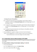
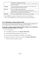
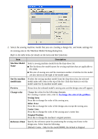
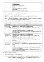
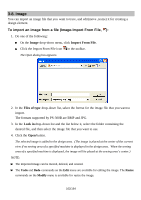
position.) Original Position: The machine's original position. Center: The center position of the sewing area Upper Left: The upper left corner of the sewing area 3. Click the OK button to apply the specified settings. 4. Specify the position of the sewing area The sewing area frame appears and the pointer is set on the selected reference point. NOTE: If the frame does not appear, scroll the mouse wheel to reduce the view size of the design area, then move the pointer to check if the frame appears. NOTE: If the machine model B856E, ZE856A or ZE8580 is selected, the frame will not appear. To specify the frame position correctly, follow one of the methods below. Method Result Hold down the keyboard's Shift key. When there is no design element in the design area: The frame reference point will be shifted to the X and Y origins of the coordinates. When there is design element(s) in the design area: The frame reference point will be shifted to the center of the element(s) you are currently edited. Hold down the keyboard's Ctrl key. When there is no design element in the design area: The frame reference point will be shifted to the X and Y origins of the coordinates. When there is design element(s) in the design area: The frame reference point will be shifted to the sewing start point of the element(s). Press any of the numeric keys on the keyboard. The Input Point dialog box appears. Input values of the X-Y coordinates where the frame reference point is to be shifted. NOTE: When there is another frame in the design area, the Relative Coordinate check box will be available. Check this box to specify X-Y coordinates of the relative distance from the reference point of another frame. 5. Click on the desired position. The sewing area frame is fixed to the position. NOTE: Once the frame is pasted on the design area, it can be repositioned by clicking on it. At this time, the Relative Coordinate check box in the Input Point dialog box will be 160/164
-
 1
1 -
2
-
3
-
4
-
5
-
6
-
7
-
8
-
9
-
10
-
11
-
12
-
13
-
14
-
15
-
16
-
17
-
18
-
19
-
20
-
21
-
22
-
23
-
24
-
25
-
26
-
27
-
28
-
29
-
30
-
31
-
32
-
33
-
34
-
35
-
36
-
37
-
38
-
39
-
40
-
41
-
42
-
43
-
44
-
45
-
46
-
47
-
48
-
49
-
50
-
51
-
52
-
53
-
54
-
55
-
56
-
57
-
58
-
59
-
60
-
61
-
62
-
63
-
64
-
65
-
66
-
67
-
68
-
69
-
70
-
71
-
72
-
73
-
74
-
75
-
76
-
77
-
78
-
79
-
80
-
81
-
82
-
83
-
84
-
85
-
86
-
87
-
88
-
89
-
90
-
91
-
92
-
93
-
94
-
95
-
96
-
97
-
98
-
99
-
100
-
101
-
102
-
103
-
104
-
105
-
106
-
107
-
108
-
109
-
110
-
111
-
112
-
113
-
114
-
115
-
116
-
117
-
118
-
119
-
120
-
121
-
122
-
123
-
124
-
125
-
126
-
127
-
128
-
129
-
130
-
131
-
132
-
133
-
134
-
135
-
136
-
137
-
138
-
139
-
140
-
141
-
142
-
143
-
144
-
145
-
146
-
147
-
148
-
149
-
150
-
151
-
152
-
153
-
154
-
 155
155 -
 156
156 -
 157
157 -
 158
158 -
 159
159 -
 160
160 -
 161
161 -
 162
162 -
 163
163 -
 164
164
 |
 |