Brother International PS-300B Instruction Manual - English - Page 4
Icons in the toolbar, Machine, Model Setting, Reference Window
 |
View all Brother International PS-300B manuals
Add to My Manuals
Save this manual to your list of manuals |
Page 4 highlights
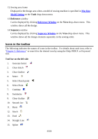
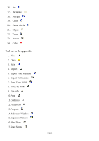
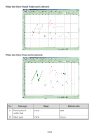
12.Sewing area frame Displayed in the design area when a model of sewing machine is specified in Machine Model Setting on the Tools drop-down menu. 13.Reference window Can be displayed by clicking Reference Windowon the View drop-down menu. This window shows all the design. 14.Sequence window Can be displayed by clicking Sequence Window on the Viewdrop-down menu. This window shows all the design elements separately in the sewing order. Icons in the toolbar The following indicates the names of icons in the toolbar. For details about each icon, refer to "Chapter 3. Reference" or search for the desired icon by using the Help INDEX or Keyword tool. Tool bar on the left side 1. Generate Select 2. Clear Stitch 3. Clear Outline 4. Select 5. Select Punch point 6. Select Point 7. Continue 8. Symmetry 9. Close Outline 10. Smooth Arc 11. Baste 12. Stitch 13. Feed 14. Straight Line 15. Spline 4/164
-
 1
1 -
 2
2 -
 3
3 -
 4
4 -
 5
5 -
 6
6 -
 7
7 -
 8
8 -
 9
9 -
 10
10 -
11
-
12
-
13
-
14
-
15
-
16
-
17
-
18
-
19
-
20
-
21
-
22
-
23
-
24
-
25
-
26
-
27
-
28
-
29
-
30
-
31
-
32
-
33
-
34
-
35
-
36
-
37
-
38
-
39
-
40
-
41
-
42
-
43
-
44
-
45
-
46
-
47
-
48
-
49
-
50
-
51
-
52
-
53
-
54
-
55
-
56
-
57
-
58
-
59
-
60
-
61
-
62
-
63
-
64
-
65
-
66
-
67
-
68
-
69
-
70
-
71
-
72
-
73
-
74
-
75
-
76
-
77
-
78
-
79
-
80
-
81
-
82
-
83
-
84
-
85
-
86
-
87
-
88
-
89
-
90
-
91
-
92
-
93
-
94
-
95
-
96
-
97
-
98
-
99
-
100
-
101
-
102
-
103
-
104
-
105
-
106
-
107
-
108
-
109
-
110
-
111
-
112
-
113
-
114
-
115
-
116
-
117
-
118
-
119
-
120
-
121
-
122
-
123
-
124
-
125
-
126
-
127
-
128
-
129
-
130
-
131
-
132
-
133
-
134
-
135
-
136
-
137
-
138
-
139
-
140
-
141
-
142
-
143
-
144
-
145
-
146
-
147
-
148
-
149
-
150
-
151
-
152
-
153
-
154
-
155
-
156
-
157
-
158
-
159
-
160
-
161
-
162
-
163
-
164
 |
 |