Brother International PS-300B Instruction Manual - English - Page 12
key, press the, On the keyboard, while holding down
 |
View all Brother International PS-300B manuals
Add to My Manuals
Save this manual to your list of manuals |
Page 12 highlights
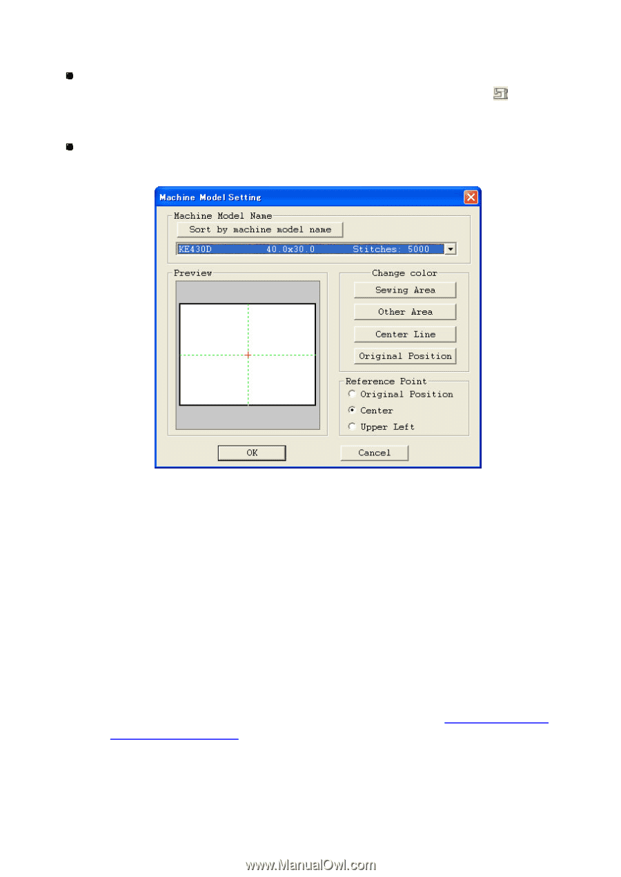
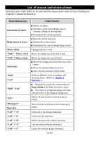
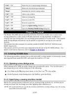
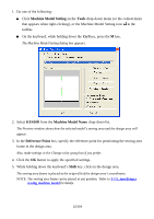
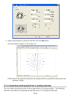
1. Do one of the following: Click Machine Model Setting on the Tools drop-down menu (or the context menu that appears when right-clicking), or the Machine Model Setting icon in the toolbar. On the keyboard, while holding down the Ctrl key, press the M key. The Machine Model Setting dialog box appears. 2. Select KE430D from the Machine Model Name drop-down list. The Preview window shows how the selected model's sewing area and the design area will appear. 3. In the Reference Point box, specify the reference point for positioning the sewing area frame in the design area. Also, make settings in th e Change color group box if you prefer. 4. Click the OK button to apply the specified settings. 5. While holding down the keyboard's Shift key, click on the design area. The sewing area frame is placed at the origin (0) of the design area's coordinates. NOTE: The sewing area frame can be placed at any position. Refer to 3-7-5. Specifying a sewing machine model for details. 12/164
-
 1
1 -
2
-
3
-
4
-
5
-
6
-
 7
7 -
 8
8 -
 9
9 -
 10
10 -
 11
11 -
 12
12 -
 13
13 -
 14
14 -
 15
15 -
 16
16 -
 17
17 -
18
-
19
-
20
-
21
-
22
-
23
-
24
-
25
-
26
-
27
-
28
-
29
-
30
-
31
-
32
-
33
-
34
-
35
-
36
-
37
-
38
-
39
-
40
-
41
-
42
-
43
-
44
-
45
-
46
-
47
-
48
-
49
-
50
-
51
-
52
-
53
-
54
-
55
-
56
-
57
-
58
-
59
-
60
-
61
-
62
-
63
-
64
-
65
-
66
-
67
-
68
-
69
-
70
-
71
-
72
-
73
-
74
-
75
-
76
-
77
-
78
-
79
-
80
-
81
-
82
-
83
-
84
-
85
-
86
-
87
-
88
-
89
-
90
-
91
-
92
-
93
-
94
-
95
-
96
-
97
-
98
-
99
-
100
-
101
-
102
-
103
-
104
-
105
-
106
-
107
-
108
-
109
-
110
-
111
-
112
-
113
-
114
-
115
-
116
-
117
-
118
-
119
-
120
-
121
-
122
-
123
-
124
-
125
-
126
-
127
-
128
-
129
-
130
-
131
-
132
-
133
-
134
-
135
-
136
-
137
-
138
-
139
-
140
-
141
-
142
-
143
-
144
-
145
-
146
-
147
-
148
-
149
-
150
-
151
-
152
-
153
-
154
-
155
-
156
-
157
-
158
-
159
-
160
-
161
-
162
-
163
-
164
 |
 |