HP StorageWorks 2/16V Brocade Web Tools Administrator's Guide - Supporting Fab - Page 173
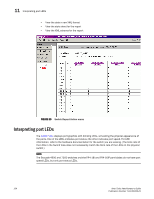
Displaying the temperature status, Temperature Sensor States window
 |
View all HP StorageWorks 2/16V manuals
Add to My Manuals
Save this manual to your list of manuals |
Page 173 highlights
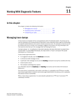
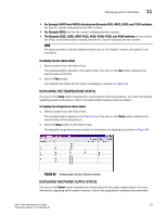
Displaying switch information 11 • For Brocade 24000 and 48000 directors and Brocade 4100, 4900, 5000, and 7500 switches, the Fan No. column indicates the fan FRU number. • For Brocade 3900, the Fan No. column indicates the fan number. • The Brocade 200E, 3250, 3850 4012, 4016, 4018, 4020, and 4024 switches do not contain fan FRUs, so for these switch models, the Fan No. column indicates the fan number. NOTE For these switches, if the Fan Status window has no "Fan Speed" column, the speed is not monitored. To display the fan status detail 1. Select a switch from the Fabric Tree. The selected switch appears in the Switch View. The icon on the Fan button indicates the overall status of the fan. 2. Click the Fan button. The detailed fan status for the switch is displayed, as shown in Figure 65. DISPLAYING THE TEMPERATURE STATUS The icon on the Temp button indicates the overall status of the temperature. For more information regarding switch temperature, refer to the appropriate hardware documentation. To display the temperature status detail 1. Select a switch from the Fabric Tree. The selected switch appears in the Switch View. The icon on the Temp button indicates the overall status of the temperature. 2. Click the Temp button on the Switch View. The detailed temperature sensor states for the switch are displayed, as shown in Figure 66. FIGURE 66 Temperature Sensor States window DISPLAYING THE POWER SUPPLY STATUS The icon on the Power button indicates the overall status of the power supply status. For more information regarding switch power modules, refer to the appropriate hardware documentation. Web Tools Administrator's Guide 151 Publication Number: 53-1000435-01
-
 1
1 -
2
-
3
-
4
-
5
-
6
-
7
-
8
-
9
-
10
-
11
-
12
-
13
-
14
-
15
-
16
-
17
-
18
-
19
-
20
-
21
-
22
-
23
-
24
-
25
-
26
-
27
-
28
-
29
-
30
-
31
-
32
-
33
-
34
-
35
-
36
-
37
-
38
-
39
-
40
-
41
-
42
-
43
-
44
-
45
-
46
-
47
-
48
-
49
-
50
-
51
-
52
-
53
-
54
-
55
-
56
-
57
-
58
-
59
-
60
-
61
-
62
-
63
-
64
-
65
-
66
-
67
-
68
-
69
-
70
-
71
-
72
-
73
-
74
-
75
-
76
-
77
-
78
-
79
-
80
-
81
-
82
-
83
-
84
-
85
-
86
-
87
-
88
-
89
-
90
-
91
-
92
-
93
-
94
-
95
-
96
-
97
-
98
-
99
-
100
-
101
-
102
-
103
-
104
-
105
-
106
-
107
-
108
-
109
-
110
-
111
-
112
-
113
-
114
-
115
-
116
-
117
-
118
-
119
-
120
-
121
-
122
-
123
-
124
-
125
-
126
-
127
-
128
-
129
-
130
-
131
-
132
-
133
-
134
-
135
-
136
-
137
-
138
-
139
-
140
-
141
-
142
-
143
-
144
-
145
-
146
-
147
-
148
-
149
-
150
-
151
-
152
-
153
-
154
-
155
-
156
-
157
-
158
-
159
-
160
-
161
-
162
-
163
-
164
-
165
-
166
-
167
-
 168
168 -
 169
169 -
 170
170 -
 171
171 -
 172
172 -
 173
173 -
 174
174 -
 175
175 -
 176
176 -
 177
177 -
 178
178 -
179
-
180
-
181
-
182
-
183
-
184
-
185
-
186
-
187
-
188
-
189
-
190
-
191
-
192
-
193
-
194
-
195
-
196
-
197
-
198
-
199
-
200
-
201
-
202
-
203
-
204
-
205
-
206
-
207
-
208
-
209
-
210
-
211
-
212
-
213
-
214
-
215
-
216
-
217
-
218
-
219
-
220
-
221
-
222
-
223
-
224
-
225
-
226
-
227
-
228
-
229
-
230
-
231
-
232
-
233
-
234
-
235
-
236
-
237
-
238
-
239
-
240
-
241
-
242
-
243
-
244
-
245
-
246
-
247
-
248
-
249
-
250
-
251
-
252
-
253
-
254
-
255
-
256
-
257
-
258
-
259
-
260
-
261
-
262
-
263
-
264
-
265
-
266
 |
 |