HP StorageWorks 2/16V Brocade Web Tools Administrator's Guide - Supporting Fab - Page 244
Configuring FMS parameters
 |
View all HP StorageWorks 2/16V manuals
Add to My Manuals
Save this manual to your list of manuals |
Page 244 highlights
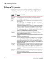
18 Configuring FMS parameters Configuring FMS parameters FMS parameters control the behavior of the switch with respect to CUP itself, as well as the behavior of other management interfaces (director console, Alternate Managers). You can configure FMS parameters for a switch only after FMS mode is enabled on the switch. All FMS parameter settings are persistent across switch power cycles. There are six FMS parameters, as described in the table below. TABLE 13 FMS Mode Parameter Descriptions Parameter Description Programmed Offline State Control Controls whether host programming is allowed to set the switch offline. The parameter is set as enabled by the hardware after system installation, and can be reset by Web Tools. Active=Saved Mode Controls the IPL file update. The IPL file saves port connectivity attributes and port names. After a switch reboot or power cycle, the switch reads the IPL file and actives its contents as default configuration. When this mode is enabled, activating a configuration saves a copy to the IPL configuration file. All changes made to the active connectivity attributes or port names by host programming or alternate managers are saved in this IPL file. It keeps the current active configuration persistent across switch reboots and power cycles. You cannot directly modify the IPL file or save a file as an IPL file. When this mode is disabled, the IPL file is not altered for either new configuration activation or any changes made on the current active configuration. This parameter is set as enabled by the hardware after system installation, and can be reset by Web Tools. Note: When FMS mode is enabled and the Active=Saved parameter is disabled, you can enable and disable ports, but the setting is not persistent. When the Active=Saved parameter is enabled, you can enable and disable ports and the setting is persistent. Alternate Control Prohibited Determines whether alternate managers are allowed to modify port connectivity. Enabling this mode prohibits alternate manager control of port connectivity; otherwise, alternate managers can manage port connectivity. This parameter is set as enabled by the hardware after system installation, and can be reset by Web Tools. User Alert Mode Controls director console behavior for alerts. Enabling this mode prompts the director consoles to display a warning whenever you attempt an action that will change switch parameters. When you disable this mode, no warning is displayed. In this case, in which Web Tools is the director console, warning messages are displayed by Web Tools regardless of the setting of the parameter, since Web Tools always displays warning messages when you apply a change to a switch that changes parameters. This parameter is always read-only in Web Tools. Each time that the switch is powered on, the parameter is reset to disabled. Director Clock Alert Mode Controls behavior for attempts to set the switch timestamp clock through the director console. When it is enabled, the director console (Web Tools, in this case) displays warning indications when the switch timestamp is changed by a user application. When it is disabled, you can activate a function to automatically set the timestamp clock. There is no indication for timestamp clock setting. This parameter is set as disabled by the hardware after system installation, and can be reset by Web Tools. Host Control Prohibited Determines whether host programming allows modifying port connectivity. Enabling this mode prohibits host programming control of port connectivity; otherwise, host programming can manage port connectivity. This parameter is set as disabled by the hardware after system installation. and can be reset by Web Tools. 222 Web Tools Administrator's Guide Publication Number: 53-1000435-01
-
 1
1 -
2
-
3
-
4
-
5
-
6
-
7
-
8
-
9
-
10
-
11
-
12
-
13
-
14
-
15
-
16
-
17
-
18
-
19
-
20
-
21
-
22
-
23
-
24
-
25
-
26
-
27
-
28
-
29
-
30
-
31
-
32
-
33
-
34
-
35
-
36
-
37
-
38
-
39
-
40
-
41
-
42
-
43
-
44
-
45
-
46
-
47
-
48
-
49
-
50
-
51
-
52
-
53
-
54
-
55
-
56
-
57
-
58
-
59
-
60
-
61
-
62
-
63
-
64
-
65
-
66
-
67
-
68
-
69
-
70
-
71
-
72
-
73
-
74
-
75
-
76
-
77
-
78
-
79
-
80
-
81
-
82
-
83
-
84
-
85
-
86
-
87
-
88
-
89
-
90
-
91
-
92
-
93
-
94
-
95
-
96
-
97
-
98
-
99
-
100
-
101
-
102
-
103
-
104
-
105
-
106
-
107
-
108
-
109
-
110
-
111
-
112
-
113
-
114
-
115
-
116
-
117
-
118
-
119
-
120
-
121
-
122
-
123
-
124
-
125
-
126
-
127
-
128
-
129
-
130
-
131
-
132
-
133
-
134
-
135
-
136
-
137
-
138
-
139
-
140
-
141
-
142
-
143
-
144
-
145
-
146
-
147
-
148
-
149
-
150
-
151
-
152
-
153
-
154
-
155
-
156
-
157
-
158
-
159
-
160
-
161
-
162
-
163
-
164
-
165
-
166
-
167
-
168
-
169
-
170
-
171
-
172
-
173
-
174
-
175
-
176
-
177
-
178
-
179
-
180
-
181
-
182
-
183
-
184
-
185
-
186
-
187
-
188
-
189
-
190
-
191
-
192
-
193
-
194
-
195
-
196
-
197
-
198
-
199
-
200
-
201
-
202
-
203
-
204
-
205
-
206
-
207
-
208
-
209
-
210
-
211
-
212
-
213
-
214
-
215
-
216
-
217
-
218
-
219
-
220
-
221
-
222
-
223
-
224
-
225
-
226
-
227
-
228
-
229
-
230
-
231
-
232
-
233
-
234
-
235
-
236
-
237
-
238
-
 239
239 -
 240
240 -
 241
241 -
 242
242 -
 243
243 -
 244
244 -
 245
245 -
 246
246 -
 247
247 -
 248
248 -
 249
249 -
250
-
251
-
252
-
253
-
254
-
255
-
256
-
257
-
258
-
259
-
260
-
261
-
262
-
263
-
264
-
265
-
266
 |
 |