Brother International PE-DESIGN 10 Instruction Manual - Page 212
Basic Design Center Operations
 |
View all Brother International PE-DESIGN 10 manuals
Add to My Manuals
Save this manual to your list of manuals |
Page 212 highlights
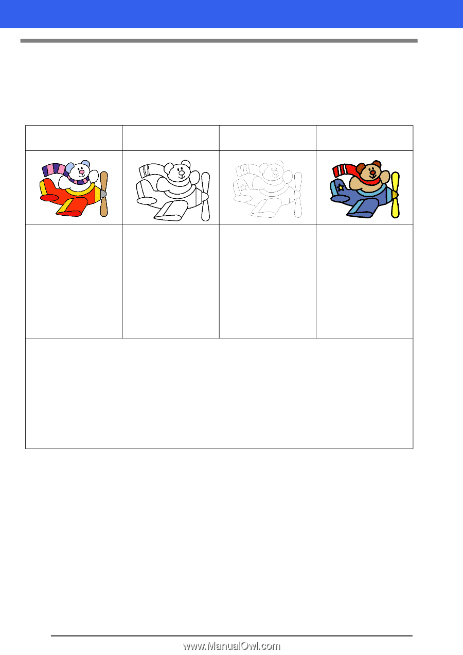
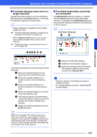
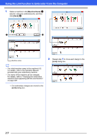
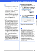
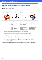
Basic Design Center Operations Basic Design Center Operations In Design Center, embroidery patterns can be created from an original image. In addition, you can specify colors and sewing attributes for the lines and regions that are more detailed than those specified with the [Auto Punch] function in Layout & Editing. An embroidery design is created in the following four stages. Step 1 Original Image Stage Step 2 Line Image Stage Step 3 Figure Handle Stage Step 4 Sew Setting Stage Open an image file, and select the colors to be used for creating the outlines. The original image is converted to a black-andwhite line image. Outlines can be drawn or erased. The line image is converted to a figure handle image. Points in the figure handle image can be edited to change the design. The sew type and thread colors are specified in the outline to complete the embroidery design. Example: The stripes in the scarf are erased. Stripes are added to the scarf. Example: The eyes are moved, and the facial expression is changed. A star is added to the tail of the plane. Example: By applying colors different than in the original image, the design is given a different appearance. • If the data is saved, work can be stopped at each stage, then started again. • The most appropriate images to use are those with few and distinct colors. Images or photos that are intricate or have gradations are not suitable since it is difficult to extract their outlines. • Line image data is saved in the .pel format, and figure handle data is saved in the .pem format. • The embroidery data is saved in the .pem format. To transfer .pem data created in Design Center to an embroidery machine, import the pattern into Layout & Editing, and then transfer the data to an embroidery machine. cc "Importing into Layout & Editing" on page 220 and "Transferring Embroidery Designs to Machines" on page 201 This section describes the basic operations performed in Design Center. For details on the procedures or settings, refer to "Design Center Window" on page 221. 211
-
 1
1 -
2
-
3
-
4
-
5
-
6
-
7
-
8
-
9
-
10
-
11
-
12
-
13
-
14
-
15
-
16
-
17
-
18
-
19
-
20
-
21
-
22
-
23
-
24
-
25
-
26
-
27
-
28
-
29
-
30
-
31
-
32
-
33
-
34
-
35
-
36
-
37
-
38
-
39
-
40
-
41
-
42
-
43
-
44
-
45
-
46
-
47
-
48
-
49
-
50
-
51
-
52
-
53
-
54
-
55
-
56
-
57
-
58
-
59
-
60
-
61
-
62
-
63
-
64
-
65
-
66
-
67
-
68
-
69
-
70
-
71
-
72
-
73
-
74
-
75
-
76
-
77
-
78
-
79
-
80
-
81
-
82
-
83
-
84
-
85
-
86
-
87
-
88
-
89
-
90
-
91
-
92
-
93
-
94
-
95
-
96
-
97
-
98
-
99
-
100
-
101
-
102
-
103
-
104
-
105
-
106
-
107
-
108
-
109
-
110
-
111
-
112
-
113
-
114
-
115
-
116
-
117
-
118
-
119
-
120
-
121
-
122
-
123
-
124
-
125
-
126
-
127
-
128
-
129
-
130
-
131
-
132
-
133
-
134
-
135
-
136
-
137
-
138
-
139
-
140
-
141
-
142
-
143
-
144
-
145
-
146
-
147
-
148
-
149
-
150
-
151
-
152
-
153
-
154
-
155
-
156
-
157
-
158
-
159
-
160
-
161
-
162
-
163
-
164
-
165
-
166
-
167
-
168
-
169
-
170
-
171
-
172
-
173
-
174
-
175
-
176
-
177
-
178
-
179
-
180
-
181
-
182
-
183
-
184
-
185
-
186
-
187
-
188
-
189
-
190
-
191
-
192
-
193
-
194
-
195
-
196
-
197
-
198
-
199
-
200
-
201
-
202
-
203
-
204
-
205
-
206
-
 207
207 -
 208
208 -
 209
209 -
 210
210 -
 211
211 -
 212
212 -
 213
213 -
 214
214 -
 215
215 -
 216
216 -
 217
217 -
218
-
219
-
220
-
221
-
222
-
223
-
224
-
225
-
226
-
227
-
228
-
229
-
230
-
231
-
232
-
233
-
234
-
235
-
236
-
237
-
238
-
239
-
240
-
241
-
242
-
243
-
244
-
245
-
246
-
247
-
248
-
249
-
250
-
251
-
252
-
253
-
254
-
255
-
256
-
257
-
258
-
259
-
260
-
261
-
262
-
263
-
264
-
265
-
266
-
267
-
268
-
269
-
270
-
271
-
272
-
273
-
274
-
275
-
276
-
277
-
278
-
279
-
280
-
281
-
282
-
283
-
284
-
285
-
286
-
287
-
288
-
289
-
290
-
291
-
292
-
293
-
294
-
295
-
296
-
297
-
298
-
299
-
300
-
301
-
302
-
303
-
304
-
305
-
306
-
307
-
308
-
309
-
310
-
311
-
312
-
313
-
314
-
315
-
316
-
317
-
318
-
319
-
320
-
321
-
322
-
323
-
324
-
325
-
326
-
327
-
328
-
329
-
330
-
331
-
332
-
333
-
334
-
335
-
336
-
337
-
338
-
339
-
340
-
341
-
342
-
343
-
344
-
345
-
346
-
347
-
348
-
349
-
350
-
351
-
352
-
353
 |
 |