Brother International PE-DESIGN Ver.6 Users Manual - English - Page 158
Specifying the geometric, attribute
 |
View all Brother International PE-DESIGN Ver.6 manuals
Add to My Manuals
Save this manual to your list of manuals |
Page 158 highlights
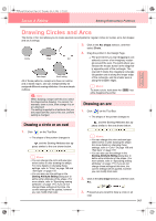
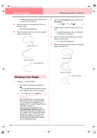
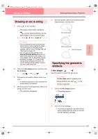
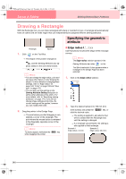
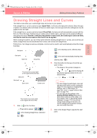
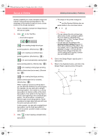
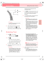
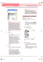
PeDesignV6Eng.book Page 150 Thursday, July 8, 2004 11:59 AM Layout & Editing 4. Click in the Design Page to specify the next point. b Memo: To remove the last point that was entered, click the right mouse button. 5. Continue clicking to specify every point, and then double-click the last end point. a Note: • While drawing the pattern, you can freely switch between the different line types either by clicking a different button or by pressing the shortcut key. • Even after the pattern is drawn, you can transform straight lines into curves and vice versa. For more details, refer to "Transforming straight lines into curves or curves into straight lines" on page 137. • If Close Path is set, double-clicking will automatically draw a line between the last and the first points of the line. • When drawing a straight line, hold down the Shift key while moving the pointer to draw vertically or horizontally. • A template image is needed in order to draw using the Semi-Automatic tool. If there is no image, this tool will draw like the Straight Line tool. Specifying the geometric attribute ■ Path shape Use this selector to select whether the broken lines and curves will be open or closed. b Memo: The Path shape selector appears in the Sewing Attributes bar when on the Tool Box is selected. It also appears when a broken line or curve in the Design Page has been selected. 1. Click the Path shape selector. → The settings appear. 2. Click the desired option. 150 Editing Embroidery Patterns → The setting is applied to all patterns that will be created with the Outline tools, until the setting is changed. → If a broken line or curve was selected, the setting is also applied to that broken line or curve.
-
 1
1 -
2
-
3
-
4
-
5
-
6
-
7
-
8
-
9
-
10
-
11
-
12
-
13
-
14
-
15
-
16
-
17
-
18
-
19
-
20
-
21
-
22
-
23
-
24
-
25
-
26
-
27
-
28
-
29
-
30
-
31
-
32
-
33
-
34
-
35
-
36
-
37
-
38
-
39
-
40
-
41
-
42
-
43
-
44
-
45
-
46
-
47
-
48
-
49
-
50
-
51
-
52
-
53
-
54
-
55
-
56
-
57
-
58
-
59
-
60
-
61
-
62
-
63
-
64
-
65
-
66
-
67
-
68
-
69
-
70
-
71
-
72
-
73
-
74
-
75
-
76
-
77
-
78
-
79
-
80
-
81
-
82
-
83
-
84
-
85
-
86
-
87
-
88
-
89
-
90
-
91
-
92
-
93
-
94
-
95
-
96
-
97
-
98
-
99
-
100
-
101
-
102
-
103
-
104
-
105
-
106
-
107
-
108
-
109
-
110
-
111
-
112
-
113
-
114
-
115
-
116
-
117
-
118
-
119
-
120
-
121
-
122
-
123
-
124
-
125
-
126
-
127
-
128
-
129
-
130
-
131
-
132
-
133
-
134
-
135
-
136
-
137
-
138
-
139
-
140
-
141
-
142
-
143
-
144
-
145
-
146
-
147
-
148
-
149
-
150
-
151
-
152
-
 153
153 -
 154
154 -
 155
155 -
 156
156 -
 157
157 -
 158
158 -
 159
159 -
 160
160 -
 161
161 -
 162
162 -
 163
163 -
164
-
165
-
166
-
167
-
168
-
169
-
170
-
171
-
172
-
173
-
174
-
175
-
176
-
177
-
178
-
179
-
180
-
181
-
182
-
183
-
184
-
185
-
186
-
187
-
188
-
189
-
190
-
191
-
192
-
193
-
194
-
195
-
196
-
197
-
198
-
199
-
200
-
201
-
202
-
203
-
204
-
205
-
206
-
207
-
208
-
209
-
210
-
211
-
212
-
213
-
214
-
215
-
216
-
217
-
218
-
219
-
220
-
221
-
222
-
223
-
224
-
225
-
226
-
227
-
228
-
229
-
230
-
231
-
232
-
233
-
234
-
235
-
236
-
237
-
238
-
239
-
240
-
241
-
242
-
243
-
244
-
245
-
246
-
247
-
248
-
249
-
250
-
251
-
252
-
253
-
254
-
255
-
256
-
257
-
258
-
259
-
260
-
261
-
262
-
263
-
264
-
265
-
266
-
267
-
268
-
269
-
270
-
271
-
272
 |
 |
