Dell Force10 S25N-S50N FTOS Command Line Reference Guide FTOS 8.4.2.7 E-Series - Page 1397
Description, show interfaces, Table 55-2., Lines in show controllers, Command Example continued
 |
View all Dell Force10 S25N-S50N manuals
Add to My Manuals
Save this manual to your list of manuals |
Page 1397 highlights
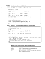
Table 55-2. Lines in show controllers interface Command Example (continued) Line LOS BIP(B1) LINE AIS RDI BIP(B2) PATH AIS RDI BIP(B3) Active Defects: Active Alarms Alarm reporting enabled for: Description Displays the loss of signal (LOS) error. This error is detected when an all-zeros pattern on the incoming interface signal lasts 19 plus or minus 3 microseconds or longer. This defect might also be reported if the received signal level drops below the specified threshold. Displays the bit interleaved parity error for the B1 byte. For B1, the report is calculated by comparing the BIP-8 code with the BIP-8 code extracted from the B1 byte of the following frame. Differences indicate section-level errors. Displays the alarm indication signal. This signal is sent by the section terminating equipment (STE) to alert the downstream line terminating equipment (LTE) that a LOS or LOF defect has been detected on the incoming interface section. Path alarm indication signal is sent by the LTE to alert the downstream path terminating equipment (PTE) that it has detected a defect on its incoming line signal. Displays remote defect indication. This indication is reported by the downstream LTE when it detects LOF, LOS, or AIS conditions. Displays the bit interleaved parity error for the B2 byte. For B2, the report is calculated by comparing the BIP-8/24 code with the BIP-8 code extracted from the B2 byte of the following frame.Differences indicate line-level errors. Displays the alarm indication signal. This signal is sent by the section terminating equipment (STE) to alert the downstream line terminating equipment (LTE) that a LOS or LOF defect has been detected on the incoming SONET section. Path alarm indication signal is sent by the LTE to alert the downstream path terminating equipment (PTE) that it has detected a defect on its incoming line signal. Displays remote defect indication. This indication is reported by the downstream LTE when it detects LOF, LOS, or AIS conditions. Displays the bit interleaved parity error for the B3 byte. For B3, the bit interleaved parity error report is calculated by comparing the BIP-8 code with the BIP-8 code extracted from the B3 byte of the following frame. Differences indicate path-level errors. Lists the current interface defects. List the current interface alarms as enforced the interface Alarm Hierarchy. List the alarms enabled. Enabled alarms generate trap reports. show interfaces e Display detailed information on the Sonet or 10-Gigabit Ethernet interfaces. Syntax show interfaces interface SONET | 1397
-
 1
1 -
2
-
3
-
4
-
5
-
6
-
7
-
8
-
9
-
10
-
11
-
12
-
13
-
14
-
15
-
16
-
17
-
18
-
19
-
20
-
21
-
22
-
23
-
24
-
25
-
26
-
27
-
28
-
29
-
30
-
31
-
32
-
33
-
34
-
35
-
36
-
37
-
38
-
39
-
40
-
41
-
42
-
43
-
44
-
45
-
46
-
47
-
48
-
49
-
50
-
51
-
52
-
53
-
54
-
55
-
56
-
57
-
58
-
59
-
60
-
61
-
62
-
63
-
64
-
65
-
66
-
67
-
68
-
69
-
70
-
71
-
72
-
73
-
74
-
75
-
76
-
77
-
78
-
79
-
80
-
81
-
82
-
83
-
84
-
85
-
86
-
87
-
88
-
89
-
90
-
91
-
92
-
93
-
94
-
95
-
96
-
97
-
98
-
99
-
100
-
101
-
102
-
103
-
104
-
105
-
106
-
107
-
108
-
109
-
110
-
111
-
112
-
113
-
114
-
115
-
116
-
117
-
118
-
119
-
120
-
121
-
122
-
123
-
124
-
125
-
126
-
127
-
128
-
129
-
130
-
131
-
132
-
133
-
134
-
135
-
136
-
137
-
138
-
139
-
140
-
141
-
142
-
143
-
144
-
145
-
146
-
147
-
148
-
149
-
150
-
151
-
152
-
153
-
154
-
155
-
156
-
157
-
158
-
159
-
160
-
161
-
162
-
163
-
164
-
165
-
166
-
167
-
168
-
169
-
170
-
171
-
172
-
173
-
174
-
175
-
176
-
177
-
178
-
179
-
180
-
181
-
182
-
183
-
184
-
185
-
186
-
187
-
188
-
189
-
190
-
191
-
192
-
193
-
194
-
195
-
196
-
197
-
198
-
199
-
200
-
201
-
202
-
203
-
204
-
205
-
206
-
207
-
208
-
209
-
210
-
211
-
212
-
213
-
214
-
215
-
216
-
217
-
218
-
219
-
220
-
221
-
222
-
223
-
224
-
225
-
226
-
227
-
228
-
229
-
230
-
231
-
232
-
233
-
234
-
235
-
236
-
237
-
238
-
239
-
240
-
241
-
242
-
243
-
244
-
245
-
246
-
247
-
248
-
249
-
250
-
251
-
252
-
253
-
254
-
255
-
256
-
257
-
258
-
259
-
260
-
261
-
262
-
263
-
264
-
265
-
266
-
267
-
268
-
269
-
270
-
271
-
272
-
273
-
274
-
275
-
276
-
277
-
278
-
279
-
280
-
281
-
282
-
283
-
284
-
285
-
286
-
287
-
288
-
289
-
290
-
291
-
292
-
293
-
294
-
295
-
296
-
297
-
298
-
299
-
300
-
301
-
302
-
303
-
304
-
305
-
306
-
307
-
308
-
309
-
310
-
311
-
312
-
313
-
314
-
315
-
316
-
317
-
318
-
319
-
320
-
321
-
322
-
323
-
324
-
325
-
326
-
327
-
328
-
329
-
330
-
331
-
332
-
333
-
334
-
335
-
336
-
337
-
338
-
339
-
340
-
341
-
342
-
343
-
344
-
345
-
346
-
347
-
348
-
349
-
350
-
351
-
352
-
353
-
354
-
355
-
356
-
357
-
358
-
359
-
360
-
361
-
362
-
363
-
364
-
365
-
366
-
367
-
368
-
369
-
370
-
371
-
372
-
373
-
374
-
375
-
376
-
377
-
378
-
379
-
380
-
381
-
382
-
383
-
384
-
385
-
386
-
387
-
388
-
389
-
390
-
391
-
392
-
393
-
394
-
395
-
396
-
397
-
398
-
399
-
400
-
401
-
402
-
403
-
404
-
405
-
406
-
407
-
408
-
409
-
410
-
411
-
412
-
413
-
414
-
415
-
416
-
417
-
418
-
419
-
420
-
421
-
422
-
423
-
424
-
425
-
426
-
427
-
428
-
429
-
430
-
431
-
432
-
433
-
434
-
435
-
436
-
437
-
438
-
439
-
440
-
441
-
442
-
443
-
444
-
445
-
446
-
447
-
448
-
449
-
450
-
451
-
452
-
453
-
454
-
455
-
456
-
457
-
458
-
459
-
460
-
461
-
462
-
463
-
464
-
465
-
466
-
467
-
468
-
469
-
470
-
471
-
472
-
473
-
474
-
475
-
476
-
477
-
478
-
479
-
480
-
481
-
482
-
483
-
484
-
485
-
486
-
487
-
488
-
489
-
490
-
491
-
492
-
493
-
494
-
495
-
496
-
497
-
498
-
499
-
500
-
501
-
502
-
503
-
504
-
505
-
506
-
507
-
508
-
509
-
510
-
511
-
512
-
513
-
514
-
515
-
516
-
517
-
518
-
519
-
520
-
521
-
522
-
523
-
524
-
525
-
526
-
527
-
528
-
529
-
530
-
531
-
532
-
533
-
534
-
535
-
536
-
537
-
538
-
539
-
540
-
541
-
542
-
543
-
544
-
545
-
546
-
547
-
548
-
549
-
550
-
551
-
552
-
553
-
554
-
555
-
556
-
557
-
558
-
559
-
560
-
561
-
562
-
563
-
564
-
565
-
566
-
567
-
568
-
569
-
570
-
571
-
572
-
573
-
574
-
575
-
576
-
577
-
578
-
579
-
580
-
581
-
582
-
583
-
584
-
585
-
586
-
587
-
588
-
589
-
590
-
591
-
592
-
593
-
594
-
595
-
596
-
597
-
598
-
599
-
600
-
601
-
602
-
603
-
604
-
605
-
606
-
607
-
608
-
609
-
610
-
611
-
612
-
613
-
614
-
615
-
616
-
617
-
618
-
619
-
620
-
621
-
622
-
623
-
624
-
625
-
626
-
627
-
628
-
629
-
630
-
631
-
632
-
633
-
634
-
635
-
636
-
637
-
638
-
639
-
640
-
641
-
642
-
643
-
644
-
645
-
646
-
647
-
648
-
649
-
650
-
651
-
652
-
653
-
654
-
655
-
656
-
657
-
658
-
659
-
660
-
661
-
662
-
663
-
664
-
665
-
666
-
667
-
668
-
669
-
670
-
671
-
672
-
673
-
674
-
675
-
676
-
677
-
678
-
679
-
680
-
681
-
682
-
683
-
684
-
685
-
686
-
687
-
688
-
689
-
690
-
691
-
692
-
693
-
694
-
695
-
696
-
697
-
698
-
699
-
700
-
701
-
702
-
703
-
704
-
705
-
706
-
707
-
708
-
709
-
710
-
711
-
712
-
713
-
714
-
715
-
716
-
717
-
718
-
719
-
720
-
721
-
722
-
723
-
724
-
725
-
726
-
727
-
728
-
729
-
730
-
731
-
732
-
733
-
734
-
735
-
736
-
737
-
738
-
739
-
740
-
741
-
742
-
743
-
744
-
745
-
746
-
747
-
748
-
749
-
750
-
751
-
752
-
753
-
754
-
755
-
756
-
757
-
758
-
759
-
760
-
761
-
762
-
763
-
764
-
765
-
766
-
767
-
768
-
769
-
770
-
771
-
772
-
773
-
774
-
775
-
776
-
777
-
778
-
779
-
780
-
781
-
782
-
783
-
784
-
785
-
786
-
787
-
788
-
789
-
790
-
791
-
792
-
793
-
794
-
795
-
796
-
797
-
798
-
799
-
800
-
801
-
802
-
803
-
804
-
805
-
806
-
807
-
808
-
809
-
810
-
811
-
812
-
813
-
814
-
815
-
816
-
817
-
818
-
819
-
820
-
821
-
822
-
823
-
824
-
825
-
826
-
827
-
828
-
829
-
830
-
831
-
832
-
833
-
834
-
835
-
836
-
837
-
838
-
839
-
840
-
841
-
842
-
843
-
844
-
845
-
846
-
847
-
848
-
849
-
850
-
851
-
852
-
853
-
854
-
855
-
856
-
857
-
858
-
859
-
860
-
861
-
862
-
863
-
864
-
865
-
866
-
867
-
868
-
869
-
870
-
871
-
872
-
873
-
874
-
875
-
876
-
877
-
878
-
879
-
880
-
881
-
882
-
883
-
884
-
885
-
886
-
887
-
888
-
889
-
890
-
891
-
892
-
893
-
894
-
895
-
896
-
897
-
898
-
899
-
900
-
901
-
902
-
903
-
904
-
905
-
906
-
907
-
908
-
909
-
910
-
911
-
912
-
913
-
914
-
915
-
916
-
917
-
918
-
919
-
920
-
921
-
922
-
923
-
924
-
925
-
926
-
927
-
928
-
929
-
930
-
931
-
932
-
933
-
934
-
935
-
936
-
937
-
938
-
939
-
940
-
941
-
942
-
943
-
944
-
945
-
946
-
947
-
948
-
949
-
950
-
951
-
952
-
953
-
954
-
955
-
956
-
957
-
958
-
959
-
960
-
961
-
962
-
963
-
964
-
965
-
966
-
967
-
968
-
969
-
970
-
971
-
972
-
973
-
974
-
975
-
976
-
977
-
978
-
979
-
980
-
981
-
982
-
983
-
984
-
985
-
986
-
987
-
988
-
989
-
990
-
991
-
992
-
993
-
994
-
995
-
996
-
997
-
998
-
999
-
1,000
-
1,001
-
1,002
-
1,003
-
1,004
-
1,005
-
1,006
-
1,007
-
1,008
-
1,009
-
1,010
-
1,011
-
1,012
-
1,013
-
1,014
-
1,015
-
1,016
-
1,017
-
1,018
-
1,019
-
1,020
-
1,021
-
1,022
-
1,023
-
1,024
-
1,025
-
1,026
-
1,027
-
1,028
-
1,029
-
1,030
-
1,031
-
1,032
-
1,033
-
1,034
-
1,035
-
1,036
-
1,037
-
1,038
-
1,039
-
1,040
-
1,041
-
1,042
-
1,043
-
1,044
-
1,045
-
1,046
-
1,047
-
1,048
-
1,049
-
1,050
-
1,051
-
1,052
-
1,053
-
1,054
-
1,055
-
1,056
-
1,057
-
1,058
-
1,059
-
1,060
-
1,061
-
1,062
-
1,063
-
1,064
-
1,065
-
1,066
-
1,067
-
1,068
-
1,069
-
1,070
-
1,071
-
1,072
-
1,073
-
1,074
-
1,075
-
1,076
-
1,077
-
1,078
-
1,079
-
1,080
-
1,081
-
1,082
-
1,083
-
1,084
-
1,085
-
1,086
-
1,087
-
1,088
-
1,089
-
1,090
-
1,091
-
1,092
-
1,093
-
1,094
-
1,095
-
1,096
-
1,097
-
1,098
-
1,099
-
1,100
-
1,101
-
1,102
-
1,103
-
1,104
-
1,105
-
1,106
-
1,107
-
1,108
-
1,109
-
1,110
-
1,111
-
1,112
-
1,113
-
1,114
-
1,115
-
1,116
-
1,117
-
1,118
-
1,119
-
1,120
-
1,121
-
1,122
-
1,123
-
1,124
-
1,125
-
1,126
-
1,127
-
1,128
-
1,129
-
1,130
-
1,131
-
1,132
-
1,133
-
1,134
-
1,135
-
1,136
-
1,137
-
1,138
-
1,139
-
1,140
-
1,141
-
1,142
-
1,143
-
1,144
-
1,145
-
1,146
-
1,147
-
1,148
-
1,149
-
1,150
-
1,151
-
1,152
-
1,153
-
1,154
-
1,155
-
1,156
-
1,157
-
1,158
-
1,159
-
1,160
-
1,161
-
1,162
-
1,163
-
1,164
-
1,165
-
1,166
-
1,167
-
1,168
-
1,169
-
1,170
-
1,171
-
1,172
-
1,173
-
1,174
-
1,175
-
1,176
-
1,177
-
1,178
-
1,179
-
1,180
-
1,181
-
1,182
-
1,183
-
1,184
-
1,185
-
1,186
-
1,187
-
1,188
-
1,189
-
1,190
-
1,191
-
1,192
-
1,193
-
1,194
-
1,195
-
1,196
-
1,197
-
1,198
-
1,199
-
1,200
-
1,201
-
1,202
-
1,203
-
1,204
-
1,205
-
1,206
-
1,207
-
1,208
-
1,209
-
1,210
-
1,211
-
1,212
-
1,213
-
1,214
-
1,215
-
1,216
-
1,217
-
1,218
-
1,219
-
1,220
-
1,221
-
1,222
-
1,223
-
1,224
-
1,225
-
1,226
-
1,227
-
1,228
-
1,229
-
1,230
-
1,231
-
1,232
-
1,233
-
1,234
-
1,235
-
1,236
-
1,237
-
1,238
-
1,239
-
1,240
-
1,241
-
1,242
-
1,243
-
1,244
-
1,245
-
1,246
-
1,247
-
1,248
-
1,249
-
1,250
-
1,251
-
1,252
-
1,253
-
1,254
-
1,255
-
1,256
-
1,257
-
1,258
-
1,259
-
1,260
-
1,261
-
1,262
-
1,263
-
1,264
-
1,265
-
1,266
-
1,267
-
1,268
-
1,269
-
1,270
-
1,271
-
1,272
-
1,273
-
1,274
-
1,275
-
1,276
-
1,277
-
1,278
-
1,279
-
1,280
-
1,281
-
1,282
-
1,283
-
1,284
-
1,285
-
1,286
-
1,287
-
1,288
-
1,289
-
1,290
-
1,291
-
1,292
-
1,293
-
1,294
-
1,295
-
1,296
-
1,297
-
1,298
-
1,299
-
1,300
-
1,301
-
1,302
-
1,303
-
1,304
-
1,305
-
1,306
-
1,307
-
1,308
-
1,309
-
1,310
-
1,311
-
1,312
-
1,313
-
1,314
-
1,315
-
1,316
-
1,317
-
1,318
-
1,319
-
1,320
-
1,321
-
1,322
-
1,323
-
1,324
-
1,325
-
1,326
-
1,327
-
1,328
-
1,329
-
1,330
-
1,331
-
1,332
-
1,333
-
1,334
-
1,335
-
1,336
-
1,337
-
1,338
-
1,339
-
1,340
-
1,341
-
1,342
-
1,343
-
1,344
-
1,345
-
1,346
-
1,347
-
1,348
-
1,349
-
1,350
-
1,351
-
1,352
-
1,353
-
1,354
-
1,355
-
1,356
-
1,357
-
1,358
-
1,359
-
1,360
-
1,361
-
1,362
-
1,363
-
1,364
-
1,365
-
1,366
-
1,367
-
1,368
-
1,369
-
1,370
-
1,371
-
1,372
-
1,373
-
1,374
-
1,375
-
1,376
-
1,377
-
1,378
-
1,379
-
1,380
-
1,381
-
1,382
-
1,383
-
1,384
-
1,385
-
1,386
-
1,387
-
1,388
-
1,389
-
1,390
-
1,391
-
 1,392
1,392 -
 1,393
1,393 -
 1,394
1,394 -
 1,395
1,395 -
 1,396
1,396 -
 1,397
1,397 -
 1,398
1,398 -
 1,399
1,399 -
 1,400
1,400 -
 1,401
1,401 -
 1,402
1,402 -
1,403
-
1,404
-
1,405
-
1,406
-
1,407
-
1,408
-
1,409
-
1,410
-
1,411
-
1,412
-
1,413
-
1,414
-
1,415
-
1,416
-
1,417
-
1,418
-
1,419
-
1,420
-
1,421
-
1,422
-
1,423
-
1,424
-
1,425
-
1,426
-
1,427
-
1,428
-
1,429
-
1,430
-
1,431
-
1,432
-
1,433
-
1,434
-
1,435
-
1,436
-
1,437
-
1,438
-
1,439
-
1,440
-
1,441
-
1,442
-
1,443
-
1,444
-
1,445
-
1,446
-
1,447
-
1,448
-
1,449
-
1,450
-
1,451
-
1,452
-
1,453
-
1,454
-
1,455
-
1,456
-
1,457
-
1,458
-
1,459
-
1,460
-
1,461
-
1,462
-
1,463
-
1,464
-
1,465
-
1,466
-
1,467
-
1,468
-
1,469
-
1,470
-
1,471
-
1,472
-
1,473
-
1,474
-
1,475
-
1,476
-
1,477
-
1,478
-
1,479
-
1,480
-
1,481
-
1,482
-
1,483
-
1,484
-
1,485
-
1,486
-
1,487
-
1,488
-
1,489
-
1,490
-
1,491
-
1,492
-
1,493
-
1,494
-
1,495
-
1,496
-
1,497
-
1,498
-
1,499
-
1,500
-
1,501
-
1,502
-
1,503
-
1,504
-
1,505
-
1,506
-
1,507
-
1,508
-
1,509
-
1,510
-
1,511
-
1,512
-
1,513
-
1,514
-
1,515
-
1,516
-
1,517
-
1,518
-
1,519
-
1,520
-
1,521
-
1,522
-
1,523
-
1,524
-
1,525
-
1,526
-
1,527
-
1,528
-
1,529
-
1,530
-
1,531
-
1,532
-
1,533
-
1,534
-
1,535
-
1,536
-
1,537
-
1,538
-
1,539
-
1,540
-
1,541
-
1,542
-
1,543
-
1,544
-
1,545
-
1,546
-
1,547
-
1,548
-
1,549
-
1,550
-
1,551
-
1,552
-
1,553
-
1,554
-
1,555
-
1,556
-
1,557
-
1,558
-
1,559
-
1,560
-
1,561
-
1,562
-
1,563
-
1,564
-
1,565
-
1,566
-
1,567
-
1,568
-
1,569
-
1,570
-
1,571
-
1,572
-
1,573
-
1,574
-
1,575
-
1,576
-
1,577
-
1,578
-
1,579
-
1,580
-
1,581
-
1,582
-
1,583
-
1,584
-
1,585
-
1,586
-
1,587
-
1,588
-
1,589
-
1,590
-
1,591
-
1,592
-
1,593
-
1,594
-
1,595
-
1,596
-
1,597
-
1,598
-
1,599
-
1,600
-
1,601
-
1,602
-
1,603
-
1,604
-
1,605
-
1,606
-
1,607
-
1,608
-
1,609
-
1,610
-
1,611
-
1,612
-
1,613
-
1,614
-
1,615
-
1,616
-
1,617
-
1,618
-
1,619
-
1,620
-
1,621
-
1,622
-
1,623
-
1,624
-
1,625
-
1,626
-
1,627
-
1,628
-
1,629
-
1,630
-
1,631
-
1,632
-
1,633
-
1,634
-
1,635
-
1,636
-
1,637
-
1,638
-
1,639
-
1,640
 |
 |
