Dell Force10 S25N-S50N FTOS Command Line Reference Guide FTOS 8.4.2.7 E-Series - Page 1572
show logging driverlog, Lines in show interfaces tengigabitethernet Command Example
 |
View all Dell Force10 S25N-S50N manuals
Add to My Manuals
Save this manual to your list of manuals |
Page 1572 highlights
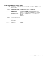
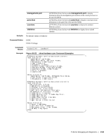
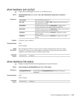
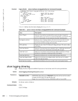
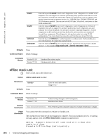
www.dell.com | support.dell.com Example Figure 65-25. show interfaces tengigabitethernet Command Example FTOS#show interfaces tengigabitethernet 4/0 link-status Port Status Loss of Signal : FALSE (XFP has power) RX Signal Lock Error : TRUE (Lock detected) PCS Link State : Down Link Faults Remote : None (No Fault) Local : Fault (Fault present) Idle Error : False (Not received) Illegal Symbol : False (Not received) Error Symbol : False (Not received) FTOS# Table 65-3 defines the information displayed in Figure 65-25. Table 65-3. Lines in show interfaces tengigabitethernet Command Example Line Loss of Signal Rx Signal Lock Error PCS Link State Link Fault Remote. Link Fault Local. Link Fault Idle Error Link Fault Illegal Symbol Link Fault Error Symbol. Description Indicates if the interface has detected the required number of digital bit transitions (from 1 to 0 and 0 to 1) on the incoming signal. A 10 GE link must detect a certain number of such transitions for proper synchronization. Indicates a loss of timing condition. The receive clock must be recovered from the incoming data stream to allow the receiving physical layer to synchronize with the incoming electrical pulses. Display the state of the PCS (Physical Coding sub-layer). The state is either up or down. Indicates if the remote device has detected a fault, is inhibiting transmission of frames, and may be continuously transmitting idle messages. Indicates if a local fault is detected that may inhibit transmission of frames, and may be continuously transmitting remote fault signals. Indicates the detections of a non-idle symbol during an idle period. Indicates the detections of an illegal symbol, other than an error symbol, while receiving data frames. Indicates the detections of an error symbol while receiving data frames. show logging driverlog e Display the driver log for the RPM CP processor or for the line card CPU in the specified slot. Syntax show logging driverlog [linecard number] Parameters linecard number (OPTIONAL) Enter the keyword linecard followed by the line card slot number to display the driver log for the specified line card. Range: 0 to 13 on a E1200, 0 to 6 on a E600/E600i, and 0 to 5 on an E300 Defaults No default values or behavior Command Modes EXEC EXEC Privilege 1572 | E-Series Debugging and Diagnostics
-
 1
1 -
2
-
3
-
4
-
5
-
6
-
7
-
8
-
9
-
10
-
11
-
12
-
13
-
14
-
15
-
16
-
17
-
18
-
19
-
20
-
21
-
22
-
23
-
24
-
25
-
26
-
27
-
28
-
29
-
30
-
31
-
32
-
33
-
34
-
35
-
36
-
37
-
38
-
39
-
40
-
41
-
42
-
43
-
44
-
45
-
46
-
47
-
48
-
49
-
50
-
51
-
52
-
53
-
54
-
55
-
56
-
57
-
58
-
59
-
60
-
61
-
62
-
63
-
64
-
65
-
66
-
67
-
68
-
69
-
70
-
71
-
72
-
73
-
74
-
75
-
76
-
77
-
78
-
79
-
80
-
81
-
82
-
83
-
84
-
85
-
86
-
87
-
88
-
89
-
90
-
91
-
92
-
93
-
94
-
95
-
96
-
97
-
98
-
99
-
100
-
101
-
102
-
103
-
104
-
105
-
106
-
107
-
108
-
109
-
110
-
111
-
112
-
113
-
114
-
115
-
116
-
117
-
118
-
119
-
120
-
121
-
122
-
123
-
124
-
125
-
126
-
127
-
128
-
129
-
130
-
131
-
132
-
133
-
134
-
135
-
136
-
137
-
138
-
139
-
140
-
141
-
142
-
143
-
144
-
145
-
146
-
147
-
148
-
149
-
150
-
151
-
152
-
153
-
154
-
155
-
156
-
157
-
158
-
159
-
160
-
161
-
162
-
163
-
164
-
165
-
166
-
167
-
168
-
169
-
170
-
171
-
172
-
173
-
174
-
175
-
176
-
177
-
178
-
179
-
180
-
181
-
182
-
183
-
184
-
185
-
186
-
187
-
188
-
189
-
190
-
191
-
192
-
193
-
194
-
195
-
196
-
197
-
198
-
199
-
200
-
201
-
202
-
203
-
204
-
205
-
206
-
207
-
208
-
209
-
210
-
211
-
212
-
213
-
214
-
215
-
216
-
217
-
218
-
219
-
220
-
221
-
222
-
223
-
224
-
225
-
226
-
227
-
228
-
229
-
230
-
231
-
232
-
233
-
234
-
235
-
236
-
237
-
238
-
239
-
240
-
241
-
242
-
243
-
244
-
245
-
246
-
247
-
248
-
249
-
250
-
251
-
252
-
253
-
254
-
255
-
256
-
257
-
258
-
259
-
260
-
261
-
262
-
263
-
264
-
265
-
266
-
267
-
268
-
269
-
270
-
271
-
272
-
273
-
274
-
275
-
276
-
277
-
278
-
279
-
280
-
281
-
282
-
283
-
284
-
285
-
286
-
287
-
288
-
289
-
290
-
291
-
292
-
293
-
294
-
295
-
296
-
297
-
298
-
299
-
300
-
301
-
302
-
303
-
304
-
305
-
306
-
307
-
308
-
309
-
310
-
311
-
312
-
313
-
314
-
315
-
316
-
317
-
318
-
319
-
320
-
321
-
322
-
323
-
324
-
325
-
326
-
327
-
328
-
329
-
330
-
331
-
332
-
333
-
334
-
335
-
336
-
337
-
338
-
339
-
340
-
341
-
342
-
343
-
344
-
345
-
346
-
347
-
348
-
349
-
350
-
351
-
352
-
353
-
354
-
355
-
356
-
357
-
358
-
359
-
360
-
361
-
362
-
363
-
364
-
365
-
366
-
367
-
368
-
369
-
370
-
371
-
372
-
373
-
374
-
375
-
376
-
377
-
378
-
379
-
380
-
381
-
382
-
383
-
384
-
385
-
386
-
387
-
388
-
389
-
390
-
391
-
392
-
393
-
394
-
395
-
396
-
397
-
398
-
399
-
400
-
401
-
402
-
403
-
404
-
405
-
406
-
407
-
408
-
409
-
410
-
411
-
412
-
413
-
414
-
415
-
416
-
417
-
418
-
419
-
420
-
421
-
422
-
423
-
424
-
425
-
426
-
427
-
428
-
429
-
430
-
431
-
432
-
433
-
434
-
435
-
436
-
437
-
438
-
439
-
440
-
441
-
442
-
443
-
444
-
445
-
446
-
447
-
448
-
449
-
450
-
451
-
452
-
453
-
454
-
455
-
456
-
457
-
458
-
459
-
460
-
461
-
462
-
463
-
464
-
465
-
466
-
467
-
468
-
469
-
470
-
471
-
472
-
473
-
474
-
475
-
476
-
477
-
478
-
479
-
480
-
481
-
482
-
483
-
484
-
485
-
486
-
487
-
488
-
489
-
490
-
491
-
492
-
493
-
494
-
495
-
496
-
497
-
498
-
499
-
500
-
501
-
502
-
503
-
504
-
505
-
506
-
507
-
508
-
509
-
510
-
511
-
512
-
513
-
514
-
515
-
516
-
517
-
518
-
519
-
520
-
521
-
522
-
523
-
524
-
525
-
526
-
527
-
528
-
529
-
530
-
531
-
532
-
533
-
534
-
535
-
536
-
537
-
538
-
539
-
540
-
541
-
542
-
543
-
544
-
545
-
546
-
547
-
548
-
549
-
550
-
551
-
552
-
553
-
554
-
555
-
556
-
557
-
558
-
559
-
560
-
561
-
562
-
563
-
564
-
565
-
566
-
567
-
568
-
569
-
570
-
571
-
572
-
573
-
574
-
575
-
576
-
577
-
578
-
579
-
580
-
581
-
582
-
583
-
584
-
585
-
586
-
587
-
588
-
589
-
590
-
591
-
592
-
593
-
594
-
595
-
596
-
597
-
598
-
599
-
600
-
601
-
602
-
603
-
604
-
605
-
606
-
607
-
608
-
609
-
610
-
611
-
612
-
613
-
614
-
615
-
616
-
617
-
618
-
619
-
620
-
621
-
622
-
623
-
624
-
625
-
626
-
627
-
628
-
629
-
630
-
631
-
632
-
633
-
634
-
635
-
636
-
637
-
638
-
639
-
640
-
641
-
642
-
643
-
644
-
645
-
646
-
647
-
648
-
649
-
650
-
651
-
652
-
653
-
654
-
655
-
656
-
657
-
658
-
659
-
660
-
661
-
662
-
663
-
664
-
665
-
666
-
667
-
668
-
669
-
670
-
671
-
672
-
673
-
674
-
675
-
676
-
677
-
678
-
679
-
680
-
681
-
682
-
683
-
684
-
685
-
686
-
687
-
688
-
689
-
690
-
691
-
692
-
693
-
694
-
695
-
696
-
697
-
698
-
699
-
700
-
701
-
702
-
703
-
704
-
705
-
706
-
707
-
708
-
709
-
710
-
711
-
712
-
713
-
714
-
715
-
716
-
717
-
718
-
719
-
720
-
721
-
722
-
723
-
724
-
725
-
726
-
727
-
728
-
729
-
730
-
731
-
732
-
733
-
734
-
735
-
736
-
737
-
738
-
739
-
740
-
741
-
742
-
743
-
744
-
745
-
746
-
747
-
748
-
749
-
750
-
751
-
752
-
753
-
754
-
755
-
756
-
757
-
758
-
759
-
760
-
761
-
762
-
763
-
764
-
765
-
766
-
767
-
768
-
769
-
770
-
771
-
772
-
773
-
774
-
775
-
776
-
777
-
778
-
779
-
780
-
781
-
782
-
783
-
784
-
785
-
786
-
787
-
788
-
789
-
790
-
791
-
792
-
793
-
794
-
795
-
796
-
797
-
798
-
799
-
800
-
801
-
802
-
803
-
804
-
805
-
806
-
807
-
808
-
809
-
810
-
811
-
812
-
813
-
814
-
815
-
816
-
817
-
818
-
819
-
820
-
821
-
822
-
823
-
824
-
825
-
826
-
827
-
828
-
829
-
830
-
831
-
832
-
833
-
834
-
835
-
836
-
837
-
838
-
839
-
840
-
841
-
842
-
843
-
844
-
845
-
846
-
847
-
848
-
849
-
850
-
851
-
852
-
853
-
854
-
855
-
856
-
857
-
858
-
859
-
860
-
861
-
862
-
863
-
864
-
865
-
866
-
867
-
868
-
869
-
870
-
871
-
872
-
873
-
874
-
875
-
876
-
877
-
878
-
879
-
880
-
881
-
882
-
883
-
884
-
885
-
886
-
887
-
888
-
889
-
890
-
891
-
892
-
893
-
894
-
895
-
896
-
897
-
898
-
899
-
900
-
901
-
902
-
903
-
904
-
905
-
906
-
907
-
908
-
909
-
910
-
911
-
912
-
913
-
914
-
915
-
916
-
917
-
918
-
919
-
920
-
921
-
922
-
923
-
924
-
925
-
926
-
927
-
928
-
929
-
930
-
931
-
932
-
933
-
934
-
935
-
936
-
937
-
938
-
939
-
940
-
941
-
942
-
943
-
944
-
945
-
946
-
947
-
948
-
949
-
950
-
951
-
952
-
953
-
954
-
955
-
956
-
957
-
958
-
959
-
960
-
961
-
962
-
963
-
964
-
965
-
966
-
967
-
968
-
969
-
970
-
971
-
972
-
973
-
974
-
975
-
976
-
977
-
978
-
979
-
980
-
981
-
982
-
983
-
984
-
985
-
986
-
987
-
988
-
989
-
990
-
991
-
992
-
993
-
994
-
995
-
996
-
997
-
998
-
999
-
1,000
-
1,001
-
1,002
-
1,003
-
1,004
-
1,005
-
1,006
-
1,007
-
1,008
-
1,009
-
1,010
-
1,011
-
1,012
-
1,013
-
1,014
-
1,015
-
1,016
-
1,017
-
1,018
-
1,019
-
1,020
-
1,021
-
1,022
-
1,023
-
1,024
-
1,025
-
1,026
-
1,027
-
1,028
-
1,029
-
1,030
-
1,031
-
1,032
-
1,033
-
1,034
-
1,035
-
1,036
-
1,037
-
1,038
-
1,039
-
1,040
-
1,041
-
1,042
-
1,043
-
1,044
-
1,045
-
1,046
-
1,047
-
1,048
-
1,049
-
1,050
-
1,051
-
1,052
-
1,053
-
1,054
-
1,055
-
1,056
-
1,057
-
1,058
-
1,059
-
1,060
-
1,061
-
1,062
-
1,063
-
1,064
-
1,065
-
1,066
-
1,067
-
1,068
-
1,069
-
1,070
-
1,071
-
1,072
-
1,073
-
1,074
-
1,075
-
1,076
-
1,077
-
1,078
-
1,079
-
1,080
-
1,081
-
1,082
-
1,083
-
1,084
-
1,085
-
1,086
-
1,087
-
1,088
-
1,089
-
1,090
-
1,091
-
1,092
-
1,093
-
1,094
-
1,095
-
1,096
-
1,097
-
1,098
-
1,099
-
1,100
-
1,101
-
1,102
-
1,103
-
1,104
-
1,105
-
1,106
-
1,107
-
1,108
-
1,109
-
1,110
-
1,111
-
1,112
-
1,113
-
1,114
-
1,115
-
1,116
-
1,117
-
1,118
-
1,119
-
1,120
-
1,121
-
1,122
-
1,123
-
1,124
-
1,125
-
1,126
-
1,127
-
1,128
-
1,129
-
1,130
-
1,131
-
1,132
-
1,133
-
1,134
-
1,135
-
1,136
-
1,137
-
1,138
-
1,139
-
1,140
-
1,141
-
1,142
-
1,143
-
1,144
-
1,145
-
1,146
-
1,147
-
1,148
-
1,149
-
1,150
-
1,151
-
1,152
-
1,153
-
1,154
-
1,155
-
1,156
-
1,157
-
1,158
-
1,159
-
1,160
-
1,161
-
1,162
-
1,163
-
1,164
-
1,165
-
1,166
-
1,167
-
1,168
-
1,169
-
1,170
-
1,171
-
1,172
-
1,173
-
1,174
-
1,175
-
1,176
-
1,177
-
1,178
-
1,179
-
1,180
-
1,181
-
1,182
-
1,183
-
1,184
-
1,185
-
1,186
-
1,187
-
1,188
-
1,189
-
1,190
-
1,191
-
1,192
-
1,193
-
1,194
-
1,195
-
1,196
-
1,197
-
1,198
-
1,199
-
1,200
-
1,201
-
1,202
-
1,203
-
1,204
-
1,205
-
1,206
-
1,207
-
1,208
-
1,209
-
1,210
-
1,211
-
1,212
-
1,213
-
1,214
-
1,215
-
1,216
-
1,217
-
1,218
-
1,219
-
1,220
-
1,221
-
1,222
-
1,223
-
1,224
-
1,225
-
1,226
-
1,227
-
1,228
-
1,229
-
1,230
-
1,231
-
1,232
-
1,233
-
1,234
-
1,235
-
1,236
-
1,237
-
1,238
-
1,239
-
1,240
-
1,241
-
1,242
-
1,243
-
1,244
-
1,245
-
1,246
-
1,247
-
1,248
-
1,249
-
1,250
-
1,251
-
1,252
-
1,253
-
1,254
-
1,255
-
1,256
-
1,257
-
1,258
-
1,259
-
1,260
-
1,261
-
1,262
-
1,263
-
1,264
-
1,265
-
1,266
-
1,267
-
1,268
-
1,269
-
1,270
-
1,271
-
1,272
-
1,273
-
1,274
-
1,275
-
1,276
-
1,277
-
1,278
-
1,279
-
1,280
-
1,281
-
1,282
-
1,283
-
1,284
-
1,285
-
1,286
-
1,287
-
1,288
-
1,289
-
1,290
-
1,291
-
1,292
-
1,293
-
1,294
-
1,295
-
1,296
-
1,297
-
1,298
-
1,299
-
1,300
-
1,301
-
1,302
-
1,303
-
1,304
-
1,305
-
1,306
-
1,307
-
1,308
-
1,309
-
1,310
-
1,311
-
1,312
-
1,313
-
1,314
-
1,315
-
1,316
-
1,317
-
1,318
-
1,319
-
1,320
-
1,321
-
1,322
-
1,323
-
1,324
-
1,325
-
1,326
-
1,327
-
1,328
-
1,329
-
1,330
-
1,331
-
1,332
-
1,333
-
1,334
-
1,335
-
1,336
-
1,337
-
1,338
-
1,339
-
1,340
-
1,341
-
1,342
-
1,343
-
1,344
-
1,345
-
1,346
-
1,347
-
1,348
-
1,349
-
1,350
-
1,351
-
1,352
-
1,353
-
1,354
-
1,355
-
1,356
-
1,357
-
1,358
-
1,359
-
1,360
-
1,361
-
1,362
-
1,363
-
1,364
-
1,365
-
1,366
-
1,367
-
1,368
-
1,369
-
1,370
-
1,371
-
1,372
-
1,373
-
1,374
-
1,375
-
1,376
-
1,377
-
1,378
-
1,379
-
1,380
-
1,381
-
1,382
-
1,383
-
1,384
-
1,385
-
1,386
-
1,387
-
1,388
-
1,389
-
1,390
-
1,391
-
1,392
-
1,393
-
1,394
-
1,395
-
1,396
-
1,397
-
1,398
-
1,399
-
1,400
-
1,401
-
1,402
-
1,403
-
1,404
-
1,405
-
1,406
-
1,407
-
1,408
-
1,409
-
1,410
-
1,411
-
1,412
-
1,413
-
1,414
-
1,415
-
1,416
-
1,417
-
1,418
-
1,419
-
1,420
-
1,421
-
1,422
-
1,423
-
1,424
-
1,425
-
1,426
-
1,427
-
1,428
-
1,429
-
1,430
-
1,431
-
1,432
-
1,433
-
1,434
-
1,435
-
1,436
-
1,437
-
1,438
-
1,439
-
1,440
-
1,441
-
1,442
-
1,443
-
1,444
-
1,445
-
1,446
-
1,447
-
1,448
-
1,449
-
1,450
-
1,451
-
1,452
-
1,453
-
1,454
-
1,455
-
1,456
-
1,457
-
1,458
-
1,459
-
1,460
-
1,461
-
1,462
-
1,463
-
1,464
-
1,465
-
1,466
-
1,467
-
1,468
-
1,469
-
1,470
-
1,471
-
1,472
-
1,473
-
1,474
-
1,475
-
1,476
-
1,477
-
1,478
-
1,479
-
1,480
-
1,481
-
1,482
-
1,483
-
1,484
-
1,485
-
1,486
-
1,487
-
1,488
-
1,489
-
1,490
-
1,491
-
1,492
-
1,493
-
1,494
-
1,495
-
1,496
-
1,497
-
1,498
-
1,499
-
1,500
-
1,501
-
1,502
-
1,503
-
1,504
-
1,505
-
1,506
-
1,507
-
1,508
-
1,509
-
1,510
-
1,511
-
1,512
-
1,513
-
1,514
-
1,515
-
1,516
-
1,517
-
1,518
-
1,519
-
1,520
-
1,521
-
1,522
-
1,523
-
1,524
-
1,525
-
1,526
-
1,527
-
1,528
-
1,529
-
1,530
-
1,531
-
1,532
-
1,533
-
1,534
-
1,535
-
1,536
-
1,537
-
1,538
-
1,539
-
1,540
-
1,541
-
1,542
-
1,543
-
1,544
-
1,545
-
1,546
-
1,547
-
1,548
-
1,549
-
1,550
-
1,551
-
1,552
-
1,553
-
1,554
-
1,555
-
1,556
-
1,557
-
1,558
-
1,559
-
1,560
-
1,561
-
1,562
-
1,563
-
1,564
-
1,565
-
1,566
-
 1,567
1,567 -
 1,568
1,568 -
 1,569
1,569 -
 1,570
1,570 -
 1,571
1,571 -
 1,572
1,572 -
 1,573
1,573 -
 1,574
1,574 -
 1,575
1,575 -
 1,576
1,576 -
 1,577
1,577 -
1,578
-
1,579
-
1,580
-
1,581
-
1,582
-
1,583
-
1,584
-
1,585
-
1,586
-
1,587
-
1,588
-
1,589
-
1,590
-
1,591
-
1,592
-
1,593
-
1,594
-
1,595
-
1,596
-
1,597
-
1,598
-
1,599
-
1,600
-
1,601
-
1,602
-
1,603
-
1,604
-
1,605
-
1,606
-
1,607
-
1,608
-
1,609
-
1,610
-
1,611
-
1,612
-
1,613
-
1,614
-
1,615
-
1,616
-
1,617
-
1,618
-
1,619
-
1,620
-
1,621
-
1,622
-
1,623
-
1,624
-
1,625
-
1,626
-
1,627
-
1,628
-
1,629
-
1,630
-
1,631
-
1,632
-
1,633
-
1,634
-
1,635
-
1,636
-
1,637
-
1,638
-
1,639
-
1,640
 |
 |
