HP DesignJet T850 DesignJet T850 Printer Series DesignJet T950 Printer SeriesU - Page 141
Small color differences between adjacent scanbars
 |
View all HP DesignJet T850 manuals
Add to My Manuals
Save this manual to your list of manuals |
Page 141 highlights
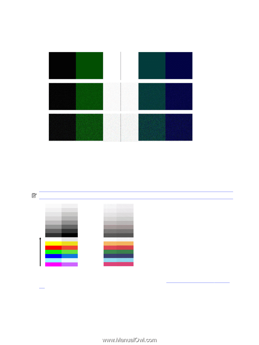
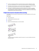
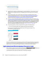
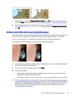
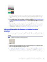
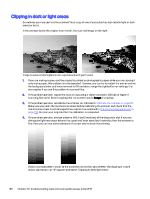
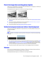
5. If the problem persists, proceed to analyze areas I and J of the diagnostic plot across modules =, 1 and 3. In the three examples below, the top example is ideal, the middle example can be regarded as acceptable; but, if you see something similar to the bottom example (or worse), call HP support and report "grain in area fills". Small color differences between adjacent scanbars When scanning wide plots, sometimes slightly different colors can be seen at both sides of the junction between two scanbars. This issue, if present, can be easily seen by analyzing patterns A and G of the diagnostic plot at the intersection between scanbars. Here are some examples: NOTE: The black arrow indicates the scanning direction. Sometimes the color mismatch between adjacent modules can be enormous, showing a serious scanner malfunction, as in the following example. If this occurs, see Completely wrong colors on page 141. 132 Chapter 16 Troubleshooting copy and scan quality issues (only MFP)
-
 1
1 -
2
-
3
-
4
-
5
-
6
-
7
-
8
-
9
-
10
-
11
-
12
-
13
-
14
-
15
-
16
-
17
-
18
-
19
-
20
-
21
-
22
-
23
-
24
-
25
-
26
-
27
-
28
-
29
-
30
-
31
-
32
-
33
-
34
-
35
-
36
-
37
-
38
-
39
-
40
-
41
-
42
-
43
-
44
-
45
-
46
-
47
-
48
-
49
-
50
-
51
-
52
-
53
-
54
-
55
-
56
-
57
-
58
-
59
-
60
-
61
-
62
-
63
-
64
-
65
-
66
-
67
-
68
-
69
-
70
-
71
-
72
-
73
-
74
-
75
-
76
-
77
-
78
-
79
-
80
-
81
-
82
-
83
-
84
-
85
-
86
-
87
-
88
-
89
-
90
-
91
-
92
-
93
-
94
-
95
-
96
-
97
-
98
-
99
-
100
-
101
-
102
-
103
-
104
-
105
-
106
-
107
-
108
-
109
-
110
-
111
-
112
-
113
-
114
-
115
-
116
-
117
-
118
-
119
-
120
-
121
-
122
-
123
-
124
-
125
-
126
-
127
-
128
-
129
-
130
-
131
-
132
-
133
-
134
-
135
-
 136
136 -
 137
137 -
 138
138 -
 139
139 -
 140
140 -
 141
141 -
 142
142 -
 143
143 -
 144
144 -
 145
145 -
 146
146 -
147
-
148
-
149
-
150
-
151
-
152
-
153
-
154
-
155
-
156
-
157
-
158
-
159
-
160
-
161
-
162
-
163
-
164
-
165
-
166
-
167
-
168
-
169
-
170
-
171
-
172
-
173
-
174
-
175
-
176
-
177
-
178
-
179
-
180
-
181
-
182
-
183
-
184
-
185
-
186
-
187
-
188
-
189
-
190
-
191
 |
 |