Intel 925 Data Sheet - Page 115
Received Target Abort Status RTAS, Master Data Parity Error PMDPE
 |
UPC - 683728067724
View all Intel 925 manuals
Add to My Manuals
Save this manual to your list of manuals |
Page 115 highlights
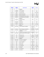
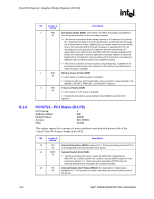
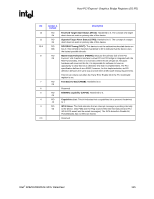
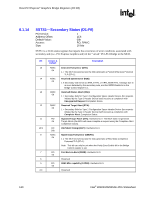
Host-PCI Express* Graphics Bridge Registers (D1:F0) R Bit Access & Default Description 12 RO Received Target Abort Status (RTAS): Hardwired to 0. The concept of a target 0b abort does not exist on primary side of this device. 11 RO Signaled Target Abort Status (STAS): Hardwired to 0. The concept of a target 0b abort does not exist on primary side of this device. 10:9 RO DEVSELB Timing (DEVT): This device is not the subtractive decoded device on 00b bus 0. This bit field is therefore hardwired to 00 to indicate that the device uses the fastest possible decode. 8 RO Master Data Parity Error (PMDPE): Because the primary side of the PCI 0b Express* x16 Graphics Interface's virtual PCI-to-PCI bridge is integrated with the MCH functionality, there is no scenario where this bit will get set. Because hardware will never set this bit, it is impossible for software to have an opportunity to clear this bit or otherwise test that it is implemented. The PCI specification defines it as a R/WC; however, for this implementation, an RO definition behaves the same way and will meet all Microsoft testing requirements. This bit can only be set when the Parity Error Enable bit in the PCI Command register is set. 7 RO Fast Back-to-Back (FB2B): Hardwired to 0. 0b 6 Reserved 5 RO 66/60MHz capability (CAP66): Hardwired to 0. 0b 4 RO Capabilities List: This bit indicates that a capabilities list is present. Hardwired 1b to 1. 3 RO INTA Status: This field indicates that an interrupt message is pending internally 0b to the device. Only PME and Hot Plug sources feed into this status bit (not PCI INTA-INTD assert and de-assert messages). The INTA Assertion Disable bit, PCICMD1[10], has no effect on this bit. 2:0 Reserved Intel® 82925X/82925XE MCH Datasheet 115
-
 1
1 -
2
-
3
-
4
-
5
-
6
-
7
-
8
-
9
-
10
-
11
-
12
-
13
-
14
-
15
-
16
-
17
-
18
-
19
-
20
-
21
-
22
-
23
-
24
-
25
-
26
-
27
-
28
-
29
-
30
-
31
-
32
-
33
-
34
-
35
-
36
-
37
-
38
-
39
-
40
-
41
-
42
-
43
-
44
-
45
-
46
-
47
-
48
-
49
-
50
-
51
-
52
-
53
-
54
-
55
-
56
-
57
-
58
-
59
-
60
-
61
-
62
-
63
-
64
-
65
-
66
-
67
-
68
-
69
-
70
-
71
-
72
-
73
-
74
-
75
-
76
-
77
-
78
-
79
-
80
-
81
-
82
-
83
-
84
-
85
-
86
-
87
-
88
-
89
-
90
-
91
-
92
-
93
-
94
-
95
-
96
-
97
-
98
-
99
-
100
-
101
-
102
-
103
-
104
-
105
-
106
-
107
-
108
-
109
-
 110
110 -
 111
111 -
 112
112 -
 113
113 -
 114
114 -
 115
115 -
 116
116 -
 117
117 -
 118
118 -
 119
119 -
 120
120 -
121
-
122
-
123
-
124
-
125
-
126
-
127
-
128
-
129
-
130
-
131
-
132
-
133
-
134
-
135
-
136
-
137
-
138
-
139
-
140
-
141
-
142
-
143
-
144
-
145
-
146
-
147
-
148
-
149
-
150
-
151
-
152
-
153
-
154
-
155
-
156
-
157
-
158
-
159
-
160
-
161
-
162
-
163
-
164
-
165
-
166
-
167
-
168
-
169
-
170
-
171
-
172
-
173
-
174
-
175
-
176
-
177
-
178
-
179
-
180
-
181
-
182
-
183
-
184
-
185
-
186
-
187
-
188
-
189
-
190
-
191
-
192
-
193
-
194
-
195
-
196
-
197
-
198
-
199
-
200
-
201
-
202
-
203
-
204
-
205
-
206
-
207
-
208
-
209
-
210
-
211
-
212
-
213
-
214
-
215
-
216
-
217
-
218
-
219
-
220
-
221
-
222
-
223
-
224
-
225
-
226
-
227
-
228
-
229
-
230
-
231
-
232
-
233
-
234
-
235
-
236
-
237
-
238
-
239
-
240
-
241
-
242
 |
 |