Intel 925 Data Sheet - Page 25
Signal Name, Description, Host Reference Voltage Reference
 |
UPC - 683728067724
View all Intel 925 manuals
Add to My Manuals
Save this manual to your list of manuals |
Page 25 highlights
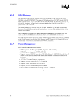
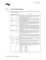
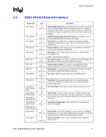
Signal Description R Signal Name HREQ[4:0]# HTRDY# HRS[2:0]# BSEL[2:0] HRCOMP HSCOMP HSWING HVREF Type I/O GTL+ 2x O GTL+ O GTL+ I CMOS I/O CMOS I/O CMOS I A I A Description Host Request Command: These signals define the attributes of the request. HREQ[4:0]# are transferred at 2x rate. They are asserted by the requesting agent during both halves of Request Phase. In the first half the signals define the transaction type to a level of detail that is sufficient to begin a snoop request. In the second half the signals carry additional information to define the complete transaction type. The transactions supported by the MCH Host Bridge are defined in the Host Interface section of this document. Host Target Ready: This signal indicates that the target of the processor transaction is able to enter the data transfer phase. Response Signals: These signals indicate the type of response as shown below: 000 = Response type 001 = Idle state 010 = Retry response 011 = Deferred response 100 = Reserved (not driven by MCH) 101 = Hard Failure (not driven by MCH) 110 = No data response 111 = Implicit Writeback 111 = Normal data response Bus Speed Select: At the de-assertion of RSTIN#, the value sampled on these pins determines the expected frequency of the bus. Host RCOMP: Used to calibrate the Host GTL+ I/O buffers. This signal is powered by the Host Interface termination rail (VTT). Slew Rate Compensation: Compensation for the Host Interface. Host Voltage Swing: This signal provides the reference voltage used by FSB RCOMP circuits. HSWING is used for the signals handled by HRCOMP. Host Reference Voltage Reference: Voltage input for the data, address, and common clock signals of the Host GTL interface. Intel® 82925X/82925XE MCH Datasheet 25
-
 1
1 -
2
-
3
-
4
-
5
-
6
-
7
-
8
-
9
-
10
-
11
-
12
-
13
-
14
-
15
-
16
-
17
-
18
-
19
-
 20
20 -
 21
21 -
 22
22 -
 23
23 -
 24
24 -
 25
25 -
 26
26 -
 27
27 -
 28
28 -
 29
29 -
 30
30 -
31
-
32
-
33
-
34
-
35
-
36
-
37
-
38
-
39
-
40
-
41
-
42
-
43
-
44
-
45
-
46
-
47
-
48
-
49
-
50
-
51
-
52
-
53
-
54
-
55
-
56
-
57
-
58
-
59
-
60
-
61
-
62
-
63
-
64
-
65
-
66
-
67
-
68
-
69
-
70
-
71
-
72
-
73
-
74
-
75
-
76
-
77
-
78
-
79
-
80
-
81
-
82
-
83
-
84
-
85
-
86
-
87
-
88
-
89
-
90
-
91
-
92
-
93
-
94
-
95
-
96
-
97
-
98
-
99
-
100
-
101
-
102
-
103
-
104
-
105
-
106
-
107
-
108
-
109
-
110
-
111
-
112
-
113
-
114
-
115
-
116
-
117
-
118
-
119
-
120
-
121
-
122
-
123
-
124
-
125
-
126
-
127
-
128
-
129
-
130
-
131
-
132
-
133
-
134
-
135
-
136
-
137
-
138
-
139
-
140
-
141
-
142
-
143
-
144
-
145
-
146
-
147
-
148
-
149
-
150
-
151
-
152
-
153
-
154
-
155
-
156
-
157
-
158
-
159
-
160
-
161
-
162
-
163
-
164
-
165
-
166
-
167
-
168
-
169
-
170
-
171
-
172
-
173
-
174
-
175
-
176
-
177
-
178
-
179
-
180
-
181
-
182
-
183
-
184
-
185
-
186
-
187
-
188
-
189
-
190
-
191
-
192
-
193
-
194
-
195
-
196
-
197
-
198
-
199
-
200
-
201
-
202
-
203
-
204
-
205
-
206
-
207
-
208
-
209
-
210
-
211
-
212
-
213
-
214
-
215
-
216
-
217
-
218
-
219
-
220
-
221
-
222
-
223
-
224
-
225
-
226
-
227
-
228
-
229
-
230
-
231
-
232
-
233
-
234
-
235
-
236
-
237
-
238
-
239
-
240
-
241
-
242
 |
 |