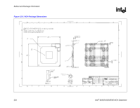
Intel 925 Data Sheet - Page 222
XOR Test Mode Initialization, XOR Chain Definition, XOR Chains, Table 13-2. XOR Chain Outputs
 |
UPC - 683728067724
View all Intel 925 manuals
Add to My Manuals
Save this manual to your list of manuals |
Page 222 highlights
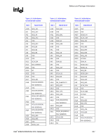
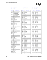
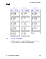
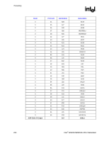
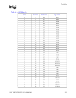
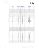
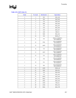
Testability R 13.2 XOR Test Mode Initialization XOR test mode can be entered by pulling reserved ballout RSV (located at F15) and MTYPE low through the de-assertion of external reset (RSTIN#). It is recommended that customers use the following sequence. After power up, hold PWROK, PCIRST#, and reserved ballout RSV (located at F15) and MTYPE low and start external clocks. After 20 cycles, pull PWROK high. After 15 clocks, deassert PCIRST# (pull it high). Release reserved ballout RSV (located at F15) and MTYPE. No external drive. Allow the clocks to run for an additional 32 clocks. Begin testing the XOR chains. 13.3 XOR Chain Definition The 82925X/82925XE MCH has 10 XOR chains. The XOR chain outputs are driven out on the following output pins. During full-width testing, XOR chain outputs will be visible on both pins. For example xor_out0 will be visible on BSEL2. Table 13-2. XOR Chain Outputs XOR Chain xor_out0 xor_out1 xor_out2 xor_out3 xor_out4 xor_out5 xor_out6 xor_out7 xor_out8 xor_out9 Output Pins BSEL2 RSV RSV MTYPE RSV RSV RSV RSV BSEL1 BSEL0 Coordinate Location D17 M16 F15 C15 A16 B15 C14 K15 E15 H16 13.4 XOR Chains The following tables show the XOR chains. The last section in this chapter has a pin exclusion list. The chain files are golden, if there is a pin missing from the chain files and exclusion list, it should be added to the exclusion list. 222 Intel® 82925X/82925XE MCH Datasheet
-
 1
1 -
2
-
3
-
4
-
5
-
6
-
7
-
8
-
9
-
10
-
11
-
12
-
13
-
14
-
15
-
16
-
17
-
18
-
19
-
20
-
21
-
22
-
23
-
24
-
25
-
26
-
27
-
28
-
29
-
30
-
31
-
32
-
33
-
34
-
35
-
36
-
37
-
38
-
39
-
40
-
41
-
42
-
43
-
44
-
45
-
46
-
47
-
48
-
49
-
50
-
51
-
52
-
53
-
54
-
55
-
56
-
57
-
58
-
59
-
60
-
61
-
62
-
63
-
64
-
65
-
66
-
67
-
68
-
69
-
70
-
71
-
72
-
73
-
74
-
75
-
76
-
77
-
78
-
79
-
80
-
81
-
82
-
83
-
84
-
85
-
86
-
87
-
88
-
89
-
90
-
91
-
92
-
93
-
94
-
95
-
96
-
97
-
98
-
99
-
100
-
101
-
102
-
103
-
104
-
105
-
106
-
107
-
108
-
109
-
110
-
111
-
112
-
113
-
114
-
115
-
116
-
117
-
118
-
119
-
120
-
121
-
122
-
123
-
124
-
125
-
126
-
127
-
128
-
129
-
130
-
131
-
132
-
133
-
134
-
135
-
136
-
137
-
138
-
139
-
140
-
141
-
142
-
143
-
144
-
145
-
146
-
147
-
148
-
149
-
150
-
151
-
152
-
153
-
154
-
155
-
156
-
157
-
158
-
159
-
160
-
161
-
162
-
163
-
164
-
165
-
166
-
167
-
168
-
169
-
170
-
171
-
172
-
173
-
174
-
175
-
176
-
177
-
178
-
179
-
180
-
181
-
182
-
183
-
184
-
185
-
186
-
187
-
188
-
189
-
190
-
191
-
192
-
193
-
194
-
195
-
196
-
197
-
198
-
199
-
200
-
201
-
202
-
203
-
204
-
205
-
206
-
207
-
208
-
209
-
210
-
211
-
212
-
213
-
214
-
215
-
216
-
 217
217 -
 218
218 -
 219
219 -
 220
220 -
 221
221 -
 222
222 -
 223
223 -
 224
224 -
 225
225 -
 226
226 -
 227
227 -
228
-
229
-
230
-
231
-
232
-
233
-
234
-
235
-
236
-
237
-
238
-
239
-
240
-
241
-
242
 |
 |