Intel 925 Data Sheet - Page 164
APIC Configuration Space FEC0_0000h-FECF_FFFFh, PCI Memory Address Range - express chipset
 |
UPC - 683728067724
View all Intel 925 manuals
Add to My Manuals
Save this manual to your list of manuals |
Page 164 highlights
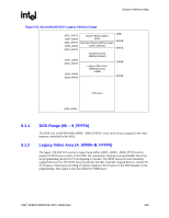
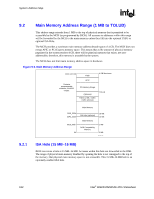
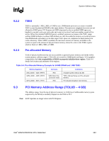
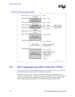
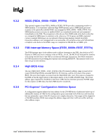
System Address Map R Figure 9-4. PCI Memory Address Range FFFF_FFFFh FFE0_0000h FEF0_0000h FEE0_0000h FED0_0000h FEC8_0000h FEC0_0000h High BIOS DMI Interface (subtractively decode) FSB Interrupts DMI Interface (subtractively decode) Local (processor) APIC I/O APIC DMI Interface (subtractively decode) 4 GB 4 GB - 2 MB 4 GB - 17 MB 4 GB - 18 MB 4 GB - 19 MB 4 GB - 20 MB Optional HSEG FEDA_0000h to FEDB_FFFFh F000_0000h PCI Express Configuration Space 4 GB - 256 MB Possible address range (Not guaranteed) E000_0000h DMI Interface (subtractively decode) 4 GB - 512 MB Programmable windows, graphics ranges, PCI Express* Port could be here TOLUD PCI_Address_Ranges_G-P-only 9.3.1 APIC Configuration Space (FEC0_0000h-FECF_FFFFh) This range is reserved for APIC configuration space. The I/O APIC(s) usually reside in the ICH6 portion of the chipset, but may also exist as stand-alone components. The IOAPIC spaces are used to communicate with IOAPIC interrupt controllers that may be populated in the system. Since it is difficult to relocate an interrupt controller using plug-and-play software, fixed address decode regions have been allocated for them. Processor accesses to the default IOAPIC region (FEC0_0000h to FEC7_FFFFh) are always forwarded to DMI. 164 Intel® 82925X/82925XE MCH Datasheet
-
 1
1 -
2
-
3
-
4
-
5
-
6
-
7
-
8
-
9
-
10
-
11
-
12
-
13
-
14
-
15
-
16
-
17
-
18
-
19
-
20
-
21
-
22
-
23
-
24
-
25
-
26
-
27
-
28
-
29
-
30
-
31
-
32
-
33
-
34
-
35
-
36
-
37
-
38
-
39
-
40
-
41
-
42
-
43
-
44
-
45
-
46
-
47
-
48
-
49
-
50
-
51
-
52
-
53
-
54
-
55
-
56
-
57
-
58
-
59
-
60
-
61
-
62
-
63
-
64
-
65
-
66
-
67
-
68
-
69
-
70
-
71
-
72
-
73
-
74
-
75
-
76
-
77
-
78
-
79
-
80
-
81
-
82
-
83
-
84
-
85
-
86
-
87
-
88
-
89
-
90
-
91
-
92
-
93
-
94
-
95
-
96
-
97
-
98
-
99
-
100
-
101
-
102
-
103
-
104
-
105
-
106
-
107
-
108
-
109
-
110
-
111
-
112
-
113
-
114
-
115
-
116
-
117
-
118
-
119
-
120
-
121
-
122
-
123
-
124
-
125
-
126
-
127
-
128
-
129
-
130
-
131
-
132
-
133
-
134
-
135
-
136
-
137
-
138
-
139
-
140
-
141
-
142
-
143
-
144
-
145
-
146
-
147
-
148
-
149
-
150
-
151
-
152
-
153
-
154
-
155
-
156
-
157
-
158
-
 159
159 -
 160
160 -
 161
161 -
 162
162 -
 163
163 -
 164
164 -
 165
165 -
 166
166 -
 167
167 -
 168
168 -
 169
169 -
170
-
171
-
172
-
173
-
174
-
175
-
176
-
177
-
178
-
179
-
180
-
181
-
182
-
183
-
184
-
185
-
186
-
187
-
188
-
189
-
190
-
191
-
192
-
193
-
194
-
195
-
196
-
197
-
198
-
199
-
200
-
201
-
202
-
203
-
204
-
205
-
206
-
207
-
208
-
209
-
210
-
211
-
212
-
213
-
214
-
215
-
216
-
217
-
218
-
219
-
220
-
221
-
222
-
223
-
224
-
225
-
226
-
227
-
228
-
229
-
230
-
231
-
232
-
233
-
234
-
235
-
236
-
237
-
238
-
239
-
240
-
241
-
242
 |
 |