| Section |
Page |
| Cisco Intrusion Prevention System Appliance and Module Installation Guide for IPS 7.0 |
1 |
| Preface |
13 |
| Contents |
13 |
| Audience |
13 |
| Comply with Local and National Electrical Codes |
13 |
| Organization |
15 |
| Conventions |
15 |
| Related Documentation |
16 |
| Obtaining Documentation and Submitting a Service Request |
17 |
| Introducing the Sensor |
19 |
| How the Sensor Functions |
19 |
| Capturing Network Traffic |
19 |
| Your Network Topology |
21 |
| Correctly Deploying the Sensor |
21 |
| Tuning the IPS |
21 |
| Sensor Interfaces |
22 |
| Understanding Sensor Interfaces |
22 |
| Command and Control Interface |
23 |
| Sensing Interfaces |
24 |
| Interface Support |
24 |
| TCP Reset Interfaces |
27 |
| Interface Restrictions |
28 |
| Interface Modes |
30 |
| Promiscuous Mode |
30 |
| IPv6, Switches, and Lack of VACL Capture |
31 |
| Inline Interface Pair Mode |
32 |
| Inline VLAN Pair Mode |
33 |
| VLAN Group Mode |
33 |
| Deploying VLAN Groups |
34 |
| Supported Sensors |
35 |
| IPS Appliances |
36 |
| Introducing the IPS Appliance |
36 |
| Appliance Restrictions |
37 |
| Connecting an Appliance to a Terminal Server |
37 |
| IPS Modules |
38 |
| Introducing the AIM IPS |
38 |
| Introducing the AIP SSM |
40 |
| Introducing the IDSM2 |
42 |
| Introducing the NME IPS |
43 |
| Time Sources and the Sensor |
44 |
| The Sensor and Time Sources |
44 |
| Synchronizing IPS Module System Clocks with the Parent Device System Clock |
46 |
| Verifying the Sensor is Synchronized with the NTP Server |
46 |
| Correcting the Time on the Sensor |
47 |
| Installation Preparation |
47 |
| Site and Safety Guidelines |
48 |
| Site Guidelines |
48 |
| Rack Configuration Guidelines |
48 |
| Electrical Safety Guidelines |
49 |
| Power Supply Guidelines |
50 |
| Working in an ESD Environment |
50 |
| Cable Pinouts |
51 |
| 10/100BaseT and 10/100/1000BaseT Connectors |
52 |
| Console Port (RJ-45) |
53 |
| RJ-45 to DB-9 or DB-25 |
54 |
| Installing the IPS 4240 and the IPS 4255 |
55 |
| Introducing the IPS 4240 and the IPS 4255 |
55 |
| Front and Back Panel Features |
56 |
| Specifications |
58 |
| Connecting the IPS 4240 to a Cisco 7200 Series Router |
59 |
| Accessories |
59 |
| Important Safety Instructions |
59 |
| Rack Mounting |
60 |
| Installing the IPS 4240 and the IPS 4255 |
61 |
| Installing the IPS 4240-DC |
64 |
| Installing the IPS 4260 |
69 |
| Introducing the IPS 4260 |
69 |
| Supported Interface Cards |
70 |
| Hardware Bypass |
72 |
| 4GE Bypass Interface Card |
72 |
| Hardware Bypass Configuration Restrictions |
73 |
| Hardware Bypass and Link Changes and Drops |
74 |
| Front and Back Panel Features |
74 |
| Specifications |
77 |
| Accessories |
77 |
| Important Safety Instructions |
78 |
| Rack Mounting |
78 |
| Installing the IPS 4260 in a 4-Post Rack |
78 |
| Installing the IPS 4260 in a 2-Post Rack |
81 |
| Installing the IPS 4260 |
83 |
| Removing and Replacing the Chassis Cover |
86 |
| Installing and Removing Interface Cards |
88 |
| Installing and Removing the Power Supply |
90 |
| Installing the IPS 4270-20 |
93 |
| Introducing the IPS 4270-20 |
94 |
| Supported Interface Cards |
95 |
| Hardware Bypass |
97 |
| 4GE Bypass Interface Card |
97 |
| Hardware Bypass Configuration Restrictions |
98 |
| Hardware Bypass and Link Changes and Drops |
99 |
| Front and Back Panel Features |
99 |
| Diagnostic Panel |
103 |
| Internal Components |
105 |
| Specifications |
106 |
| Accessories |
107 |
| Installing the Rail System Kit |
107 |
| Understanding the Rail System Kit |
107 |
| Rail System Kit Contents |
108 |
| Space and Airflow Requirements |
108 |
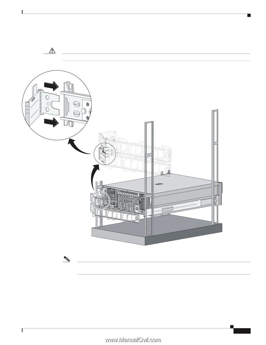
| Installing the IPS 4270-20 in the Rack |
109 |
| Extending the IPS 4270-20 from the Rack |
117 |
| Installing the Cable Management Arm |
120 |
| Converting the Cable Management Arm |
123 |
| Installing the IPS 4270-20 |
127 |
| Removing and Replacing the Chassis Cover |
130 |
| Accessing the Diagnostic Panel |
133 |
| Installing and Removing Interface Cards |
133 |
| Installing and Removing the Power Supply |
136 |
| Installing and Removing Fans |
141 |
| Troubleshooting Loose Connections |
143 |
| Installing the AIM IPS |
145 |
| Specifications |
145 |
| Before Installing the AIM IPS |
146 |
| Software and Hardware Requirements |
146 |
| Interoperability With Other IPS Modules |
147 |
| Restrictions |
147 |
| Hardware Interfaces |
148 |
| Installation and Removal Instructions |
149 |
| Verifying Installation |
150 |
| Installing the AIP SSM |
151 |
| Specifications |
151 |
| Memory Specifications |
152 |
| Hardware and Software Requirements |
152 |
| Indicators |
152 |
| Installation and Removal Instructions |
153 |
| Installing the AIP SSM |
153 |
| Verifying the Status of the AIP SSM |
154 |
| Removing the AIP SSM |
155 |
| Installing the IDSM2 |
157 |
| Specifications |
157 |
| Software and Hardware Requirements |
158 |
| Minimum Supported the IDSM2 Configurations |
158 |
| Using the TCP Reset Interface |
159 |
| Front Panel Features |
159 |
| Installation and Removal Instructions |
160 |
| Required Tools |
160 |
| Slot Assignments |
161 |
| Installing the IDSM2 |
161 |
| Verifying Installation |
165 |
| Removing the IDSM2 |
166 |
| Enabling Full Memory Tests |
168 |
| Catalyst Software |
168 |
| Cisco IOS Software |
169 |
| Resetting the IDSM2 |
169 |
| Catalyst Software |
169 |
| Cisco IOS Software |
170 |
| Powering the IDSM2 Up and Down |
171 |
| Catalyst Software |
171 |
| Cisco IOS Software |
172 |
| Installing the NME IPS |
173 |
| Specifications |
173 |
| Before Installing the NME IPS |
174 |
| Software and Hardware Requirements |
174 |
| Interoperability With Other IPS Modules |
175 |
| Restrictions |
175 |
| Hardware Interfaces |
176 |
| Installation and Removal Instructions |
177 |
| Verifying Installation |
178 |
| Logging In to the Sensor |
179 |
| Supported User Roles |
179 |
| Logging In to the Appliance |
180 |
| Connecting an Appliance to a Terminal Server |
181 |
| Logging In to the AIM IPS |
182 |
| The AIM IPS and the session Command |
182 |
| Sessioning In to the AIM IPS |
183 |
| Logging In to AIP SSM |
184 |
| Logging In to the IDSM2 |
186 |
| Logging In to the NME IPS |
187 |
| The NME IPS and the session Command |
187 |
| Sessioning In to the NME IPS |
188 |
| Logging In to the Sensor |
189 |
| Initializing the Sensor |
191 |
| Understanding Initialization |
191 |
| Simplified Setup Mode |
191 |
| System Configuration Dialog |
192 |
| Basic Sensor Setup |
194 |
| Advanced Setup |
197 |
| Advanced Setup for the Appliance |
198 |
| Advanced Setup for the AIM IPS |
203 |
| Advanced Setup for the AIP SSM |
206 |
| Advanced Setup for the IDSM2 |
210 |
| Advanced Setup for the NME IPS |
215 |
| Verifying Initialization |
218 |
| Obtaining Software |
221 |
| Obtaining Cisco IPS Software |
221 |
| IPS Software Versioning |
222 |
| Software Release Examples |
226 |
| Upgrading Cisco IPS Software to 7.0 |
227 |
| Accessing IPS Documentation |
229 |
| Cisco Security Intelligence Operations |
229 |
| Obtaining a License Key From Cisco.com |
230 |
| Understanding Licensing |
230 |
| Service Programs for IPS Products |
231 |
| Obtaining and Installing the License Key Using IDM or IME |
231 |
| Obtaining and Installing the License Key Using the CLI |
233 |
| Upgrading, Downgrading, and Installing System Images |
237 |
| Upgrades, Downgrades, and System Images |
237 |
| Supported FTP and HTTP/HTTPS Servers |
238 |
| Upgrading the Sensor |
238 |
| IPS 7.0 Upgrade Files |
238 |
| upgrade Command and Options |
239 |
| Using the upgrade Command |
240 |
| Upgrading the Recovery Partition |
241 |
| Configuring Automatic Upgrades |
242 |
| Automatic Upgrades |
242 |
| auto-upgrade Command and Options |
243 |
| Using the auto-upgrade Command |
244 |
| Automatic Upgrade Examples |
246 |
| Downgrading the Sensor |
247 |
| Recovering the Application Partition |
248 |
| Application Partition |
248 |
| Using the recover Command |
248 |
| Installing System Images |
249 |
| Understanding ROMMON |
250 |
| Supported TFTP Servers |
250 |
| Connecting an Appliance to a Terminal Server |
250 |
| Installing the IPS 4240 and IPS 4255 System Images |
251 |
| Installing the IPS 4260 System Image |
254 |
| Installing the IPS 4270-20 System Image |
256 |
| Installing the AIM IPS System Image |
259 |
| Installing the AIP SSM System Image |
261 |
| Reimaging the AIP SSM |
262 |
| Reimaging the AIP SSM Using the recover configure/boot Command |
262 |
| Installing the IDSM2 System Image |
264 |
| Understanding the IDSM2 System Image |
264 |
| Installing the IDSM2 System Image for Catalyst Software |
264 |
| Installing the IDSM2 System Image for Cisco IOS Software |
265 |
| Configuring the IDSM2 Maintenance Partition for Catalyst Software |
267 |
| Configuring the IDSM2 Maintenance Partition for Cisco IOS Software |
271 |
| Upgrading the IDSM2 Maintenance Partition for Catalyst Software |
274 |
| Upgrading the IDSM2 Maintenance Partition for Cisco IOS Software |
275 |
| Installing the NME IPS System Image |
276 |
| Troubleshooting |
279 |
| Bug Toolkit |
279 |
| Preventive Maintenance |
280 |
| Understanding Preventive Maintenance |
280 |
| Creating and Using a Backup Configuration File |
281 |
| Backing Up and Restoring the Configuration File Using a Remote Server |
281 |
| Creating the Service Account |
283 |
| Disaster Recovery |
284 |
| Recovering the Password |
285 |
| Understanding Password Recovery |
286 |
| Recovering the Appliance Password |
286 |
| Using the GRUB Menu |
286 |
| Using ROMMON |
287 |
| Recovering the AIM IPS Password |
288 |
| Recovering the AIP SSM Password |
288 |
| Recovering the IDSM2 Password |
291 |
| Recovering the NME IPS Password |
291 |
| Disabling Password Recovery |
292 |
| Verifying the State of Password Recovery |
293 |
| Troubleshooting Password Recovery |
293 |
| Time and the Sensor |
294 |
| Time Sources and the Sensor |
294 |
| Synchronizing IPS Module Clocks with Parent Device Clocks |
295 |
| Verifying the Sensor is Synchronized with the NTP Server |
295 |
| Correcting Time on the Sensor |
296 |
| Advantages and Restrictions of Virtualization |
296 |
| Supported MIBs |
297 |
| When to Disable Anomaly Detection |
298 |
| Troubleshooting Global Correlation |
298 |
| Analysis Engine Not Responding |
299 |
| Troubleshooting External Product Interfaces |
300 |
| External Product Interfaces Issues |
300 |
| External Product Interfaces Troubleshooting Tips |
301 |
| Troubleshooting the Appliance |
301 |
| Hardware Bypass and Link Changes and Drops |
302 |
| Troubleshooting Loose Connections |
302 |
| Analysis Engine is Busy |
303 |
| Connecting the IPS 4240 to a Cisco 7200 Series Router |
303 |
| Communication Problems |
304 |
| Cannot Access the Sensor CLI Through Telnet or SSH |
304 |
| Correcting a Misconfigured Access List |
306 |
| Duplicate IP Address Shuts Interface Down |
307 |
| SensorApp and Alerting |
308 |
| SensorApp Not Running |
308 |
| Physical Connectivity, SPAN, or VACL Port Issue |
310 |
| Unable to See Alerts |
311 |
| Sensor Not Seeing Packets |
313 |
| Cleaning Up a Corrupted SensorApp Configuration |
315 |
| Blocking |
315 |
| Troubleshooting Blocking |
316 |
| Verifying ARC is Running |
316 |
| Verifying ARC Connections are Active |
317 |
| Device Access Issues |
319 |
| Verifying the Interfaces and Directions on the Network Device |
321 |
| Enabling SSH Connections to the Network Device |
321 |
| Blocking Not Occurring for a Signature |
322 |
| Verifying the Master Blocking Sensor Configuration |
323 |
| Logging |
324 |
| Understanding Debug Logging |
324 |
| Enabling Debug Logging |
325 |
| Zone Names |
328 |
| Directing cidLog Messages to SysLog |
329 |
| TCP Reset Not Occurring for a Signature |
330 |
| Software Upgrades |
331 |
| Upgrading and Analysis Engine |
332 |
| Which Updates to Apply and Their Prerequisites |
332 |
| Issues With Automatic Update |
333 |
| Updating a Sensor with the Update Stored on the Sensor |
333 |
| Troubleshooting IDM |
334 |
| Cannot Launch IDM - Loading Java Applet Failed |
334 |
| Cannot Launch IDM-Analysis Engine Busy |
335 |
| IDM, Remote Manager, or Sensing Interfaces Cannot Access Sensor |
335 |
| Signatures Not Producing Alerts |
336 |
| Troubleshooting IME |
337 |
| Time Synchronization on IME and the Sensor |
337 |
| Not Supported Error Message |
337 |
| Troubleshooting the IDSM2 |
337 |
| Diagnosing IDSM2 Problems |
338 |
| Minimum Supported IDSM2 Configurations |
339 |
| Switch Commands for Troubleshooting |
339 |
| Status LED Off |
340 |
| Status LED On But the IDSM2 Does Not Come Online |
341 |
| Cannot Communicate With the IDSM2 Command and Control Port |
342 |
| Using the TCP Reset Interface |
344 |
| Connecting a Serial Cable to the IDSM2 |
344 |
| Troubleshooting the AIP SSM |
344 |
| Health and Status Information |
345 |
| The AIP SSM and the Data Plane |
347 |
| AIM SSP and the Normalizer Engine |
347 |
| Troubleshooting the AIM IPS and the NME IPS |
347 |
| Interoperability With Other IPS Network Modules |
347 |
| Gathering Information |
348 |
| Health and Network Security Information |
348 |
| Tech Support Information |
349 |
| Understanding the show tech-support Command |
349 |
| Displaying Tech Support Information |
349 |
| Tech Support Command Output |
350 |
| Version Information |
352 |
| Understanding the show version Command |
352 |
| Displaying Version Information |
352 |
| Statistics Information |
354 |
| Understanding the show statistics Command |
355 |
| Displaying Statistics |
355 |
| Interfaces Information |
365 |
| Understanding the show interfaces Command |
365 |
| Interfaces Command Output |
365 |
| Events Information |
366 |
| Sensor Events |
366 |
| Understanding the show events Command |
367 |
| Displaying Events |
367 |
| Clearing Events |
370 |
| cidDump Script |
370 |
| Uploading and Accessing Files on the Cisco FTP Site |
371 |
| Glossary |
373 |

 1
1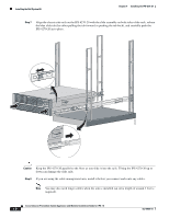 116
116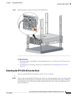 117
117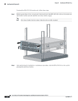 118
118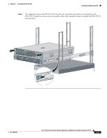 119
119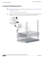 120
120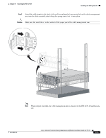 121
121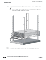 122
122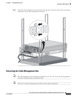 123
123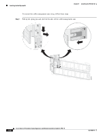 124
124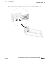 125
125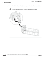 126
126