Cisco IPS-4255-K9 Installation Guide - Page 42
Introducing the IDSM2
 |
UPC - 746320951096
View all Cisco IPS-4255-K9 manuals
Add to My Manuals
Save this manual to your list of manuals |
Page 42 highlights
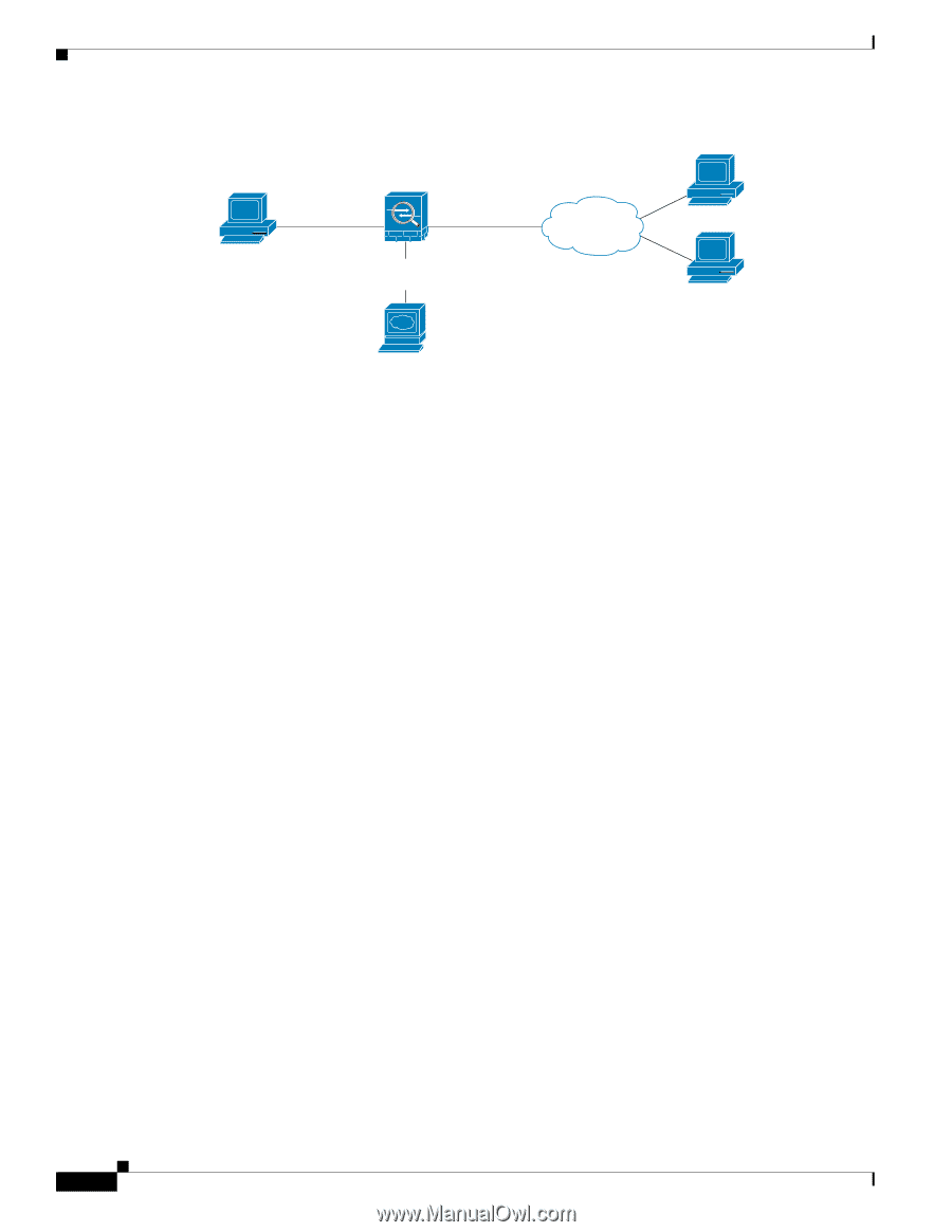
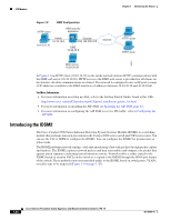
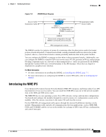
IPS Modules Chapter 1 Introducing the Sensor Figure 1-8 DMZ Configuration HTTP client ASA security appliance 10.10.10.10 Inside 10.10.10.0 Outside 209.165.200.225 DMZ 10.30.30.0 Internet HTTP client HTTP client 148403 Web server 10.30.30.30 In Figure 1-8 an HTTP client (10.10.10.10) on the inside network initiates HTTP communications with the DMZ web server (30.30.30.30). HTTP access to the DMZ web server is provided for all clients on the Internet; all other communications are denied. The network is configured to use an IP pool (a range of IP addresses available to the DMZ interface) of addresses between 30.30.30.50 and 30.30.30.60. For More Information • For more information on setting up ASA, refer to the Getting Started Guides found at this URL: http://www.cisco.com/en/US/products/ps6120/prod_installation_guides_list.html • For more information on installing the AIP SSM, see Installing the AIP SSM, page 6-3. • For more information on configuring the AIP SSM to receive IPS traffic, refer to Configuring the AIP SSM. Introducing the IDSM2 The Cisco Catalyst 6500 Series Intrusion Detection System Services Module (IDSM2) is a switching module that performs intrusion prevention in the Catalyst 6500 series switch and 7600 series router. You can use the CLI or IDSM to configure the IDSM2. You can configure the IDSM2 for promiscuous or inline mode. The IDSM2 performs network sensing-real-time monitoring of network packets through packet capture and analysis. The IDSM2 captures network packets and then reassembles and compares the packet data against attack signatures indicating typical intrusion activity. Network traffic is either copied to the IDSM2 based on security VACLs in the switch or is copied to the IDSM2 through the SPAN port feature of the switch. These methods route user-specified traffic to the IDSM2 based on switch ports, VLANs, or traffic type to be inspected (Figure 1-9 on page 1-25). 1-24 Cisco Intrusion Prevention System Appliance and Module Installation Guide for IPS 7.0 OL-18504-01
-
 1
1 -
2
-
3
-
4
-
5
-
6
-
7
-
8
-
9
-
10
-
11
-
12
-
13
-
14
-
15
-
16
-
17
-
18
-
19
-
20
-
21
-
22
-
23
-
24
-
25
-
26
-
27
-
28
-
29
-
30
-
31
-
32
-
33
-
34
-
35
-
36
-
 37
37 -
 38
38 -
 39
39 -
 40
40 -
 41
41 -
 42
42 -
 43
43 -
 44
44 -
 45
45 -
 46
46 -
 47
47 -
48
-
49
-
50
-
51
-
52
-
53
-
54
-
55
-
56
-
57
-
58
-
59
-
60
-
61
-
62
-
63
-
64
-
65
-
66
-
67
-
68
-
69
-
70
-
71
-
72
-
73
-
74
-
75
-
76
-
77
-
78
-
79
-
80
-
81
-
82
-
83
-
84
-
85
-
86
-
87
-
88
-
89
-
90
-
91
-
92
-
93
-
94
-
95
-
96
-
97
-
98
-
99
-
100
-
101
-
102
-
103
-
104
-
105
-
106
-
107
-
108
-
109
-
110
-
111
-
112
-
113
-
114
-
115
-
116
-
117
-
118
-
119
-
120
-
121
-
122
-
123
-
124
-
125
-
126
-
127
-
128
-
129
-
130
-
131
-
132
-
133
-
134
-
135
-
136
-
137
-
138
-
139
-
140
-
141
-
142
-
143
-
144
-
145
-
146
-
147
-
148
-
149
-
150
-
151
-
152
-
153
-
154
-
155
-
156
-
157
-
158
-
159
-
160
-
161
-
162
-
163
-
164
-
165
-
166
-
167
-
168
-
169
-
170
-
171
-
172
-
173
-
174
-
175
-
176
-
177
-
178
-
179
-
180
-
181
-
182
-
183
-
184
-
185
-
186
-
187
-
188
-
189
-
190
-
191
-
192
-
193
-
194
-
195
-
196
-
197
-
198
-
199
-
200
-
201
-
202
-
203
-
204
-
205
-
206
-
207
-
208
-
209
-
210
-
211
-
212
-
213
-
214
-
215
-
216
-
217
-
218
-
219
-
220
-
221
-
222
-
223
-
224
-
225
-
226
-
227
-
228
-
229
-
230
-
231
-
232
-
233
-
234
-
235
-
236
-
237
-
238
-
239
-
240
-
241
-
242
-
243
-
244
-
245
-
246
-
247
-
248
-
249
-
250
-
251
-
252
-
253
-
254
-
255
-
256
-
257
-
258
-
259
-
260
-
261
-
262
-
263
-
264
-
265
-
266
-
267
-
268
-
269
-
270
-
271
-
272
-
273
-
274
-
275
-
276
-
277
-
278
-
279
-
280
-
281
-
282
-
283
-
284
-
285
-
286
-
287
-
288
-
289
-
290
-
291
-
292
-
293
-
294
-
295
-
296
-
297
-
298
-
299
-
300
-
301
-
302
-
303
-
304
-
305
-
306
-
307
-
308
-
309
-
310
-
311
-
312
-
313
-
314
-
315
-
316
-
317
-
318
-
319
-
320
-
321
-
322
-
323
-
324
-
325
-
326
-
327
-
328
-
329
-
330
-
331
-
332
-
333
-
334
-
335
-
336
-
337
-
338
-
339
-
340
-
341
-
342
-
343
-
344
-
345
-
346
-
347
-
348
-
349
-
350
-
351
-
352
-
353
-
354
-
355
-
356
-
357
-
358
-
359
-
360
-
361
-
362
-
363
-
364
-
365
-
366
-
367
-
368
-
369
-
370
-
371
-
372
-
373
-
374
-
375
-
376
-
377
-
378
-
379
-
380
-
381
-
382
-
383
-
384
-
385
-
386
-
387
-
388
-
389
-
390
-
391
-
392
-
393
-
394
-
395
-
396
-
397
-
398
-
399
-
400
-
401
-
402
-
403
-
404
-
405
-
406
-
407
-
408
-
409
-
410
-
411
-
412
 |
 |