Cisco IPS-4255-K9 Installation Guide - Page 24
Sensing Interfaces, Interface Support, Inline VLAN Pairs Sensing
 |
UPC - 746320951096
View all Cisco IPS-4255-K9 manuals
Add to My Manuals
Save this manual to your list of manuals |
Page 24 highlights
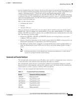
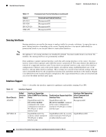
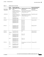
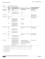
How the Sensor Functions Table 1-1 Command and Control Interfaces (continued) Sensor IPS 4255 IPS 4260 IPS 4270-20 NME IPS Command and Control Interface Management0/0 Management0/0 Management0/0 Management0/01 Chapter 1 Introducing the Sensor Sensing Interfaces Sensing interfaces are used by the sensor to analyze traffic for security violations. A sensor has one or more sensing interfaces depending on the sensor. Sensing interfaces can operate individually in promiscuous mode or you can pair them to create inline interfaces. Note On appliances, all sensing interfaces are disabled by default. You must enable them to use them. On modules, the sensing interfaces are permanently enabled. Some appliances support optional interface cards that add sensing interfaces to the sensor. You must insert or remove these optional cards while the sensor is powered off. The sensor detects the addition or removal of a supported interface card. If you remove an optional interface card, some of the interface configuration is deleted, such as the speed, duplex, description string, enabled/disabled state of the interface, and any inline interface pairings. These settings are restored to their default settings when the card is reinstalled. However, the assignment of promiscuous and inline interfaces to the Analysis Engine is not deleted from the Analysis Engine configuration, but is ignored until those cards are reinserted and you create the inline interface pairs again. Interface Support Table 1-2 describes the interface support for appliances and modules running Cisco IPS. Table 1-2 Interface Support Base Chassis AIM IPS AIP SSM-10 Added Interface Cards - - Interfaces Supporting Inline VLAN Pairs (Sensing Ports) GigabitEthernet0/1 by ids-service-module command in the router configuration instead of VLAN pair or inline interface pair GigabitEthernet0/1 by security context instead of VLAN pair or inline interface pair Interfaces Not Supporting Combinations Supporting Inline Inline (Command and Interface Pairs Control Port) GigabitEthernet0/1 by ids-service-module command in the router configuration instead of VLAN pair or inline interface pair Management0/0 GigabitEthernet0/1 by security GigabitEthernet0/0 context instead of VLAN pair or inline interface pair Cisco Intrusion Prevention System Appliance and Module Installation Guide for IPS 7.0 1-6 OL-18504-01
-
 1
1 -
2
-
3
-
4
-
5
-
6
-
7
-
8
-
9
-
10
-
11
-
12
-
13
-
14
-
15
-
16
-
17
-
18
-
 19
19 -
 20
20 -
 21
21 -
 22
22 -
 23
23 -
 24
24 -
 25
25 -
 26
26 -
 27
27 -
 28
28 -
 29
29 -
30
-
31
-
32
-
33
-
34
-
35
-
36
-
37
-
38
-
39
-
40
-
41
-
42
-
43
-
44
-
45
-
46
-
47
-
48
-
49
-
50
-
51
-
52
-
53
-
54
-
55
-
56
-
57
-
58
-
59
-
60
-
61
-
62
-
63
-
64
-
65
-
66
-
67
-
68
-
69
-
70
-
71
-
72
-
73
-
74
-
75
-
76
-
77
-
78
-
79
-
80
-
81
-
82
-
83
-
84
-
85
-
86
-
87
-
88
-
89
-
90
-
91
-
92
-
93
-
94
-
95
-
96
-
97
-
98
-
99
-
100
-
101
-
102
-
103
-
104
-
105
-
106
-
107
-
108
-
109
-
110
-
111
-
112
-
113
-
114
-
115
-
116
-
117
-
118
-
119
-
120
-
121
-
122
-
123
-
124
-
125
-
126
-
127
-
128
-
129
-
130
-
131
-
132
-
133
-
134
-
135
-
136
-
137
-
138
-
139
-
140
-
141
-
142
-
143
-
144
-
145
-
146
-
147
-
148
-
149
-
150
-
151
-
152
-
153
-
154
-
155
-
156
-
157
-
158
-
159
-
160
-
161
-
162
-
163
-
164
-
165
-
166
-
167
-
168
-
169
-
170
-
171
-
172
-
173
-
174
-
175
-
176
-
177
-
178
-
179
-
180
-
181
-
182
-
183
-
184
-
185
-
186
-
187
-
188
-
189
-
190
-
191
-
192
-
193
-
194
-
195
-
196
-
197
-
198
-
199
-
200
-
201
-
202
-
203
-
204
-
205
-
206
-
207
-
208
-
209
-
210
-
211
-
212
-
213
-
214
-
215
-
216
-
217
-
218
-
219
-
220
-
221
-
222
-
223
-
224
-
225
-
226
-
227
-
228
-
229
-
230
-
231
-
232
-
233
-
234
-
235
-
236
-
237
-
238
-
239
-
240
-
241
-
242
-
243
-
244
-
245
-
246
-
247
-
248
-
249
-
250
-
251
-
252
-
253
-
254
-
255
-
256
-
257
-
258
-
259
-
260
-
261
-
262
-
263
-
264
-
265
-
266
-
267
-
268
-
269
-
270
-
271
-
272
-
273
-
274
-
275
-
276
-
277
-
278
-
279
-
280
-
281
-
282
-
283
-
284
-
285
-
286
-
287
-
288
-
289
-
290
-
291
-
292
-
293
-
294
-
295
-
296
-
297
-
298
-
299
-
300
-
301
-
302
-
303
-
304
-
305
-
306
-
307
-
308
-
309
-
310
-
311
-
312
-
313
-
314
-
315
-
316
-
317
-
318
-
319
-
320
-
321
-
322
-
323
-
324
-
325
-
326
-
327
-
328
-
329
-
330
-
331
-
332
-
333
-
334
-
335
-
336
-
337
-
338
-
339
-
340
-
341
-
342
-
343
-
344
-
345
-
346
-
347
-
348
-
349
-
350
-
351
-
352
-
353
-
354
-
355
-
356
-
357
-
358
-
359
-
360
-
361
-
362
-
363
-
364
-
365
-
366
-
367
-
368
-
369
-
370
-
371
-
372
-
373
-
374
-
375
-
376
-
377
-
378
-
379
-
380
-
381
-
382
-
383
-
384
-
385
-
386
-
387
-
388
-
389
-
390
-
391
-
392
-
393
-
394
-
395
-
396
-
397
-
398
-
399
-
400
-
401
-
402
-
403
-
404
-
405
-
406
-
407
-
408
-
409
-
410
-
411
-
412
 |
 |
