Cisco IPS-4255-K9 Installation Guide - Page 133
Accessing the Diagnostic Panel, Installing and Removing Interface Cards
 |
UPC - 746320951096
View all Cisco IPS-4255-K9 manuals
Add to My Manuals
Save this manual to your list of manuals |
Page 133 highlights
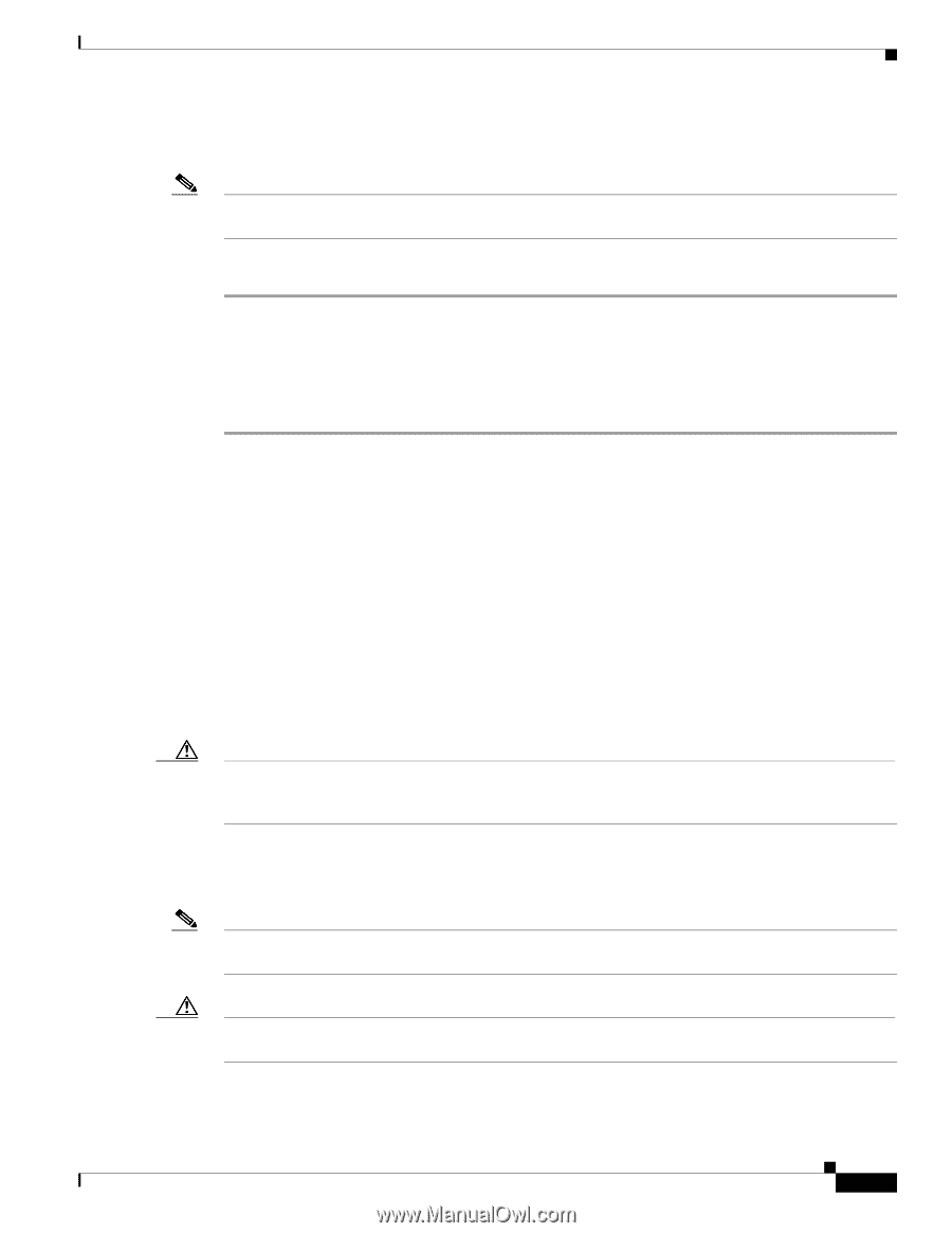
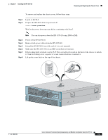
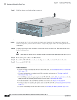
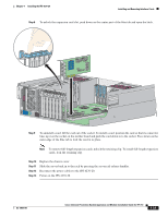
Chapter 4 Installing the IPS 4270-20 Accessing the Diagnostic Panel Accessing the Diagnostic Panel Note When you remove the chassis cover to view the Diagnostic Panel, leave the IPS 4270-20 powered on. Powering off the IPS 4270-20 clears the Diagnostic Panel indicators. To access the Diagnostic Panel, follow these steps: Step 1 Step 2 Step 3 Extend the IPS 4270-20 from the rack. Remove the chassis cover. Locate the Diagnostic Panel. Follow the instructions in this chapter to remove and install failed components. For aid in troubleshooting, use the internal health indicators information when contacting TAC. For More Information • For the procedure for extending the IPS 4270-20 from the rack, see Extending the IPS 4270-20 from the Rack, page 4-25. • For the procedure for removing the chassis cover, see Removing and Replacing the Chassis Cover, page 4-38. • For the location of the Diagnostic Panel, see Figure 4-10 on page 4-13. • For information on what internal health information each indicator displays on the Diagnostic Panel, see Diagnostic Panel, page 4-11. Installing and Removing Interface Cards Caution Follow proper safety procedures when performing these steps by reading the safety warnings in Regulatory Compliance and Safety Information for the Cisco Intrusion Prevention System 4200 Series Appliance Sensor. The IPS 4270-20 has nine expansion card slots. Slots 1 and 2 are PCI-X slots and are reserved for future use. Slots 3 through 9 are PCI-Express slots. All slots are full-height slots. Slot 9 is populated by a RAID controller card and is not available for use by network interface cards. Note The IPS 4270-20 supports two 10GE fiber interface cards, which you can install in any of the supported six slots (slots 3 to 8). Caution To prevent damage to the IPS 4270-20 or the expansion cards, power down the IPS 4270-20 and remove all AC power cables before removing or installing expansion cards. OL-18504-01 Cisco Intrusion Prevention System Appliance and Module Installation Guide for IPS 7.0 4-41
-
 1
1 -
2
-
3
-
4
-
5
-
6
-
7
-
8
-
9
-
10
-
11
-
12
-
13
-
14
-
15
-
16
-
17
-
18
-
19
-
20
-
21
-
22
-
23
-
24
-
25
-
26
-
27
-
28
-
29
-
30
-
31
-
32
-
33
-
34
-
35
-
36
-
37
-
38
-
39
-
40
-
41
-
42
-
43
-
44
-
45
-
46
-
47
-
48
-
49
-
50
-
51
-
52
-
53
-
54
-
55
-
56
-
57
-
58
-
59
-
60
-
61
-
62
-
63
-
64
-
65
-
66
-
67
-
68
-
69
-
70
-
71
-
72
-
73
-
74
-
75
-
76
-
77
-
78
-
79
-
80
-
81
-
82
-
83
-
84
-
85
-
86
-
87
-
88
-
89
-
90
-
91
-
92
-
93
-
94
-
95
-
96
-
97
-
98
-
99
-
100
-
101
-
102
-
103
-
104
-
105
-
106
-
107
-
108
-
109
-
110
-
111
-
112
-
113
-
114
-
115
-
116
-
117
-
118
-
119
-
120
-
121
-
122
-
123
-
124
-
125
-
126
-
127
-
 128
128 -
 129
129 -
 130
130 -
 131
131 -
 132
132 -
 133
133 -
 134
134 -
 135
135 -
 136
136 -
 137
137 -
 138
138 -
139
-
140
-
141
-
142
-
143
-
144
-
145
-
146
-
147
-
148
-
149
-
150
-
151
-
152
-
153
-
154
-
155
-
156
-
157
-
158
-
159
-
160
-
161
-
162
-
163
-
164
-
165
-
166
-
167
-
168
-
169
-
170
-
171
-
172
-
173
-
174
-
175
-
176
-
177
-
178
-
179
-
180
-
181
-
182
-
183
-
184
-
185
-
186
-
187
-
188
-
189
-
190
-
191
-
192
-
193
-
194
-
195
-
196
-
197
-
198
-
199
-
200
-
201
-
202
-
203
-
204
-
205
-
206
-
207
-
208
-
209
-
210
-
211
-
212
-
213
-
214
-
215
-
216
-
217
-
218
-
219
-
220
-
221
-
222
-
223
-
224
-
225
-
226
-
227
-
228
-
229
-
230
-
231
-
232
-
233
-
234
-
235
-
236
-
237
-
238
-
239
-
240
-
241
-
242
-
243
-
244
-
245
-
246
-
247
-
248
-
249
-
250
-
251
-
252
-
253
-
254
-
255
-
256
-
257
-
258
-
259
-
260
-
261
-
262
-
263
-
264
-
265
-
266
-
267
-
268
-
269
-
270
-
271
-
272
-
273
-
274
-
275
-
276
-
277
-
278
-
279
-
280
-
281
-
282
-
283
-
284
-
285
-
286
-
287
-
288
-
289
-
290
-
291
-
292
-
293
-
294
-
295
-
296
-
297
-
298
-
299
-
300
-
301
-
302
-
303
-
304
-
305
-
306
-
307
-
308
-
309
-
310
-
311
-
312
-
313
-
314
-
315
-
316
-
317
-
318
-
319
-
320
-
321
-
322
-
323
-
324
-
325
-
326
-
327
-
328
-
329
-
330
-
331
-
332
-
333
-
334
-
335
-
336
-
337
-
338
-
339
-
340
-
341
-
342
-
343
-
344
-
345
-
346
-
347
-
348
-
349
-
350
-
351
-
352
-
353
-
354
-
355
-
356
-
357
-
358
-
359
-
360
-
361
-
362
-
363
-
364
-
365
-
366
-
367
-
368
-
369
-
370
-
371
-
372
-
373
-
374
-
375
-
376
-
377
-
378
-
379
-
380
-
381
-
382
-
383
-
384
-
385
-
386
-
387
-
388
-
389
-
390
-
391
-
392
-
393
-
394
-
395
-
396
-
397
-
398
-
399
-
400
-
401
-
402
-
403
-
404
-
405
-
406
-
407
-
408
-
409
-
410
-
411
-
412
 |
 |