Cisco IPS-4255-K9 Installation Guide - Page 30
Interface Modes, Promiscuous Mode - advantage
 |
UPC - 746320951096
View all Cisco IPS-4255-K9 manuals
Add to My Manuals
Save this manual to your list of manuals |
Page 30 highlights
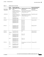
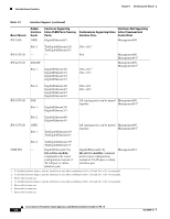
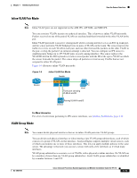
How the Sensor Functions Chapter 1 Introducing the Sensor - An interface can have no more than 255 user-defined VLAN groups. - When you pair a physical interface, you cannot subdivide it; you can subdivide the pair. - You can use a VLAN on multiple interfaces; however, you receive a warning for this configuration. - You can assign a virtual sensor to any combination of one or more physical interfaces and inline VLAN pairs, subdivided or not. - You can subdivide both physical and logical interfaces into VLAN groups. - CLI, IDM, and IME prompt you to remove any dangling references. You can leave the dangling references and continue editing the configuration. - CLI, IDM, and IME do not allow configuration changes in Analysis Engine that conflict with the interface configuration. - CLI allows configuration changes in the interface configuration that cause conflicts in the Analysis Engine configuration. IDM and IME do not allow changes in the interface configuration that cause conflicts in the Analysis Engine configuration. Interface Modes The following section describes the interface modes, and contains the following topics: • Promiscuous Mode, page 1-12 • IPv6, Switches, and Lack of VACL Capture, page 1-13 • Inline Interface Pair Mode, page 1-14 • Inline VLAN Pair Mode, page 1-15 • VLAN Group Mode, page 1-15 • Deploying VLAN Groups, page 1-16 Promiscuous Mode In promiscuous mode, packets do not flow through the sensor. The sensor analyzes a copy of the monitored traffic rather than the actual forwarded packet. The advantage of operating in promiscuous mode is that the sensor does not affect the packet flow with the forwarded traffic. The disadvantage of operating in promiscuous mode, however, is the sensor cannot stop malicious traffic from reaching its intended target for certain types of attacks, such as atomic attacks (single-packet attacks). The response actions implemented by promiscuous sensor devices are post-event responses and often require assistance from other networking devices, for example, routers and firewalls, to respond to an attack. While such response actions can prevent some classes of attacks, in atomic attacks the single packet has the chance of reaching the target system before the promiscuous-based sensor can apply an ACL modification on a managed device (such as a firewall, switch, or router). By default, all sensing interfaces are in promiscuous mode. To change an interface from inline interface mode to promiscuous mode, delete any inline interface that contains that interface and delete any inline VLAN pair subinterfaces of that interface from the interface configuration. 1-12 Cisco Intrusion Prevention System Appliance and Module Installation Guide for IPS 7.0 OL-18504-01
-
 1
1 -
2
-
3
-
4
-
5
-
6
-
7
-
8
-
9
-
10
-
11
-
12
-
13
-
14
-
15
-
16
-
17
-
18
-
19
-
20
-
21
-
22
-
23
-
24
-
 25
25 -
 26
26 -
 27
27 -
 28
28 -
 29
29 -
 30
30 -
 31
31 -
 32
32 -
 33
33 -
 34
34 -
 35
35 -
36
-
37
-
38
-
39
-
40
-
41
-
42
-
43
-
44
-
45
-
46
-
47
-
48
-
49
-
50
-
51
-
52
-
53
-
54
-
55
-
56
-
57
-
58
-
59
-
60
-
61
-
62
-
63
-
64
-
65
-
66
-
67
-
68
-
69
-
70
-
71
-
72
-
73
-
74
-
75
-
76
-
77
-
78
-
79
-
80
-
81
-
82
-
83
-
84
-
85
-
86
-
87
-
88
-
89
-
90
-
91
-
92
-
93
-
94
-
95
-
96
-
97
-
98
-
99
-
100
-
101
-
102
-
103
-
104
-
105
-
106
-
107
-
108
-
109
-
110
-
111
-
112
-
113
-
114
-
115
-
116
-
117
-
118
-
119
-
120
-
121
-
122
-
123
-
124
-
125
-
126
-
127
-
128
-
129
-
130
-
131
-
132
-
133
-
134
-
135
-
136
-
137
-
138
-
139
-
140
-
141
-
142
-
143
-
144
-
145
-
146
-
147
-
148
-
149
-
150
-
151
-
152
-
153
-
154
-
155
-
156
-
157
-
158
-
159
-
160
-
161
-
162
-
163
-
164
-
165
-
166
-
167
-
168
-
169
-
170
-
171
-
172
-
173
-
174
-
175
-
176
-
177
-
178
-
179
-
180
-
181
-
182
-
183
-
184
-
185
-
186
-
187
-
188
-
189
-
190
-
191
-
192
-
193
-
194
-
195
-
196
-
197
-
198
-
199
-
200
-
201
-
202
-
203
-
204
-
205
-
206
-
207
-
208
-
209
-
210
-
211
-
212
-
213
-
214
-
215
-
216
-
217
-
218
-
219
-
220
-
221
-
222
-
223
-
224
-
225
-
226
-
227
-
228
-
229
-
230
-
231
-
232
-
233
-
234
-
235
-
236
-
237
-
238
-
239
-
240
-
241
-
242
-
243
-
244
-
245
-
246
-
247
-
248
-
249
-
250
-
251
-
252
-
253
-
254
-
255
-
256
-
257
-
258
-
259
-
260
-
261
-
262
-
263
-
264
-
265
-
266
-
267
-
268
-
269
-
270
-
271
-
272
-
273
-
274
-
275
-
276
-
277
-
278
-
279
-
280
-
281
-
282
-
283
-
284
-
285
-
286
-
287
-
288
-
289
-
290
-
291
-
292
-
293
-
294
-
295
-
296
-
297
-
298
-
299
-
300
-
301
-
302
-
303
-
304
-
305
-
306
-
307
-
308
-
309
-
310
-
311
-
312
-
313
-
314
-
315
-
316
-
317
-
318
-
319
-
320
-
321
-
322
-
323
-
324
-
325
-
326
-
327
-
328
-
329
-
330
-
331
-
332
-
333
-
334
-
335
-
336
-
337
-
338
-
339
-
340
-
341
-
342
-
343
-
344
-
345
-
346
-
347
-
348
-
349
-
350
-
351
-
352
-
353
-
354
-
355
-
356
-
357
-
358
-
359
-
360
-
361
-
362
-
363
-
364
-
365
-
366
-
367
-
368
-
369
-
370
-
371
-
372
-
373
-
374
-
375
-
376
-
377
-
378
-
379
-
380
-
381
-
382
-
383
-
384
-
385
-
386
-
387
-
388
-
389
-
390
-
391
-
392
-
393
-
394
-
395
-
396
-
397
-
398
-
399
-
400
-
401
-
402
-
403
-
404
-
405
-
406
-
407
-
408
-
409
-
410
-
411
-
412
 |
 |