Cisco IPS-4255-K9 Installation Guide - Page 72
Hardware Bypass, 4GE Bypass Interface Card
 |
UPC - 746320951096
View all Cisco IPS-4255-K9 manuals
Add to My Manuals
Save this manual to your list of manuals |
Page 72 highlights
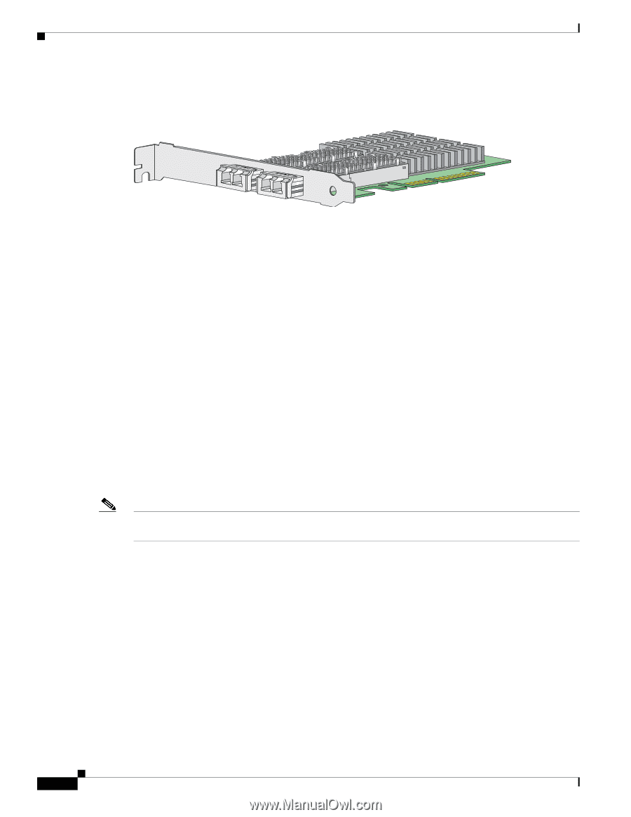
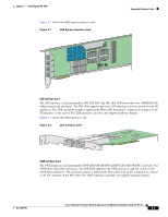
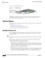
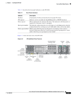
Hardware Bypass Figure 3-3 shows the 10GE interface card. Figure 3-3 10GE Interface Card Chapter 3 Installing the IPS 4260 253975 GigabitEthernetslot_number/port_number is the expansion card interface naming convention for the IPS 4260. The slot number is shown to the right of the slot in the chassis and the port number is numbered from right to left starting with 0. Hardware Bypass This section describes the 4GE bypass interface card and its configuration restrictions. It contains the following topics: • 4GE Bypass Interface Card, page 3-4 • Hardware Bypass Configuration Restrictions, page 3-5 • Hardware Bypass and Link Changes and Drops, page 3-6 4GE Bypass Interface Card The IPS 4260 supports the 4-port GigabitEthernet card (part number IPS-4GE-BP-INT=) with hardware bypass. This 4GE bypass interface card supports hardware bypass only between ports 0 and 1 and between ports 2 and 3. Note To disable hardware bypass, pair the interfaces in any other combination, for example 2/02/2 and 2/12/3. Hardware bypass complements the existing software bypass feature in Cisco IPS. The following conditions apply to hardware bypass and software bypass: • When bypass is set to OFF, software bypass is not active. For each inline interface for which hardware bypass is available, the component interfaces are set to disable the fail-open capability. If SensorApp fails, the sensor is powered off, reset, or if the NIC interface drivers fail or are unloaded, the paired interfaces enter the fail-closed state (no traffic flows through inline interface or inline VLAN subinterfaces). • When bypass is set to ON, software bypass is active. Software bypass forwards packets between the paired physical interfaces in each inline interface and between the paired VLANs in each inline VLAN subinterface. For each inline interface on which hardware bypass is available, the component interfaces are set to standby mode. If the sensor is Cisco Intrusion Prevention System Appliance and Module Installation Guide for IPS 7.0 3-4 OL-18504-01
-
 1
1 -
2
-
3
-
4
-
5
-
6
-
7
-
8
-
9
-
10
-
11
-
12
-
13
-
14
-
15
-
16
-
17
-
18
-
19
-
20
-
21
-
22
-
23
-
24
-
25
-
26
-
27
-
28
-
29
-
30
-
31
-
32
-
33
-
34
-
35
-
36
-
37
-
38
-
39
-
40
-
41
-
42
-
43
-
44
-
45
-
46
-
47
-
48
-
49
-
50
-
51
-
52
-
53
-
54
-
55
-
56
-
57
-
58
-
59
-
60
-
61
-
62
-
63
-
64
-
65
-
66
-
 67
67 -
 68
68 -
 69
69 -
 70
70 -
 71
71 -
 72
72 -
 73
73 -
 74
74 -
 75
75 -
 76
76 -
 77
77 -
78
-
79
-
80
-
81
-
82
-
83
-
84
-
85
-
86
-
87
-
88
-
89
-
90
-
91
-
92
-
93
-
94
-
95
-
96
-
97
-
98
-
99
-
100
-
101
-
102
-
103
-
104
-
105
-
106
-
107
-
108
-
109
-
110
-
111
-
112
-
113
-
114
-
115
-
116
-
117
-
118
-
119
-
120
-
121
-
122
-
123
-
124
-
125
-
126
-
127
-
128
-
129
-
130
-
131
-
132
-
133
-
134
-
135
-
136
-
137
-
138
-
139
-
140
-
141
-
142
-
143
-
144
-
145
-
146
-
147
-
148
-
149
-
150
-
151
-
152
-
153
-
154
-
155
-
156
-
157
-
158
-
159
-
160
-
161
-
162
-
163
-
164
-
165
-
166
-
167
-
168
-
169
-
170
-
171
-
172
-
173
-
174
-
175
-
176
-
177
-
178
-
179
-
180
-
181
-
182
-
183
-
184
-
185
-
186
-
187
-
188
-
189
-
190
-
191
-
192
-
193
-
194
-
195
-
196
-
197
-
198
-
199
-
200
-
201
-
202
-
203
-
204
-
205
-
206
-
207
-
208
-
209
-
210
-
211
-
212
-
213
-
214
-
215
-
216
-
217
-
218
-
219
-
220
-
221
-
222
-
223
-
224
-
225
-
226
-
227
-
228
-
229
-
230
-
231
-
232
-
233
-
234
-
235
-
236
-
237
-
238
-
239
-
240
-
241
-
242
-
243
-
244
-
245
-
246
-
247
-
248
-
249
-
250
-
251
-
252
-
253
-
254
-
255
-
256
-
257
-
258
-
259
-
260
-
261
-
262
-
263
-
264
-
265
-
266
-
267
-
268
-
269
-
270
-
271
-
272
-
273
-
274
-
275
-
276
-
277
-
278
-
279
-
280
-
281
-
282
-
283
-
284
-
285
-
286
-
287
-
288
-
289
-
290
-
291
-
292
-
293
-
294
-
295
-
296
-
297
-
298
-
299
-
300
-
301
-
302
-
303
-
304
-
305
-
306
-
307
-
308
-
309
-
310
-
311
-
312
-
313
-
314
-
315
-
316
-
317
-
318
-
319
-
320
-
321
-
322
-
323
-
324
-
325
-
326
-
327
-
328
-
329
-
330
-
331
-
332
-
333
-
334
-
335
-
336
-
337
-
338
-
339
-
340
-
341
-
342
-
343
-
344
-
345
-
346
-
347
-
348
-
349
-
350
-
351
-
352
-
353
-
354
-
355
-
356
-
357
-
358
-
359
-
360
-
361
-
362
-
363
-
364
-
365
-
366
-
367
-
368
-
369
-
370
-
371
-
372
-
373
-
374
-
375
-
376
-
377
-
378
-
379
-
380
-
381
-
382
-
383
-
384
-
385
-
386
-
387
-
388
-
389
-
390
-
391
-
392
-
393
-
394
-
395
-
396
-
397
-
398
-
399
-
400
-
401
-
402
-
403
-
404
-
405
-
406
-
407
-
408
-
409
-
410
-
411
-
412
 |
 |