Cisco IPS-4255-K9 Installation Guide - Page 33
Inline VLAN Pair Mode, VLAN Group Mode
 |
UPC - 746320951096
View all Cisco IPS-4255-K9 manuals
Add to My Manuals
Save this manual to your list of manuals |
Page 33 highlights
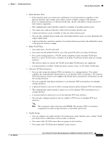
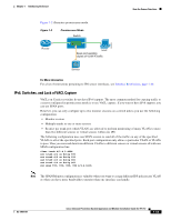
Chapter 1 Introducing the Sensor How the Sensor Functions Inline VLAN Pair Mode Note Inline VLAN pairs are not supported on the AIM IPS, AIP SSM, and NME IPS. You can associate VLANs in pairs on a physical interface. This is known as inline VLAN pair mode. Packets received on one of the paired VLANs are analyzed and then forwarded to the other VLAN in the pair. Inline VLAN pair mode is an active sensing mode where a sensing interface acts as an 802.1q trunk port, and the sensor performs VLAN bridging between pairs of VLANs on the trunk. The sensor inspects the traffic it receives on each VLAN in each pair, and can either forward the packets on the other VLAN in the pair, or drop the packet if an intrusion attempt is detected. You can configure an IPS sensor to simultaneously bridge up to 255 VLAN pairs on each sensing interface. The sensor replaces the VLAN ID field in the 802.1q header of each received packet with the ID of the egress VLAN on which the sensor forwards the packet. The sensor drops all packets received on any VLANs that are not assigned to inline VLAN pairs. Figure 1-4 illustrates inline VLAN pair mode. 253445 Figure 1-4 Router Inline VLAN Pair Mode Switch VLAN B VLAN A Host Trunk port carrying VLAN A and B Pairing VLAN A and B Sensor For More Information For a list of restrictions pertaining to IPS sensor interfaces, see Interface Restrictions, page 1-10 VLAN Group Mode Note You cannot divide physical interfaces that are in inline VLAN pairs into VLAN groups. You can divide each physical interface or inline interface into VLAN group subinterfaces, each of which consists of a group of VLANs on that interface. Analysis Engine supports multiple virtual sensors, each of which can monitor one or more of these interfaces. This lets you apply multiple policies to the same sensor. The advantage is that now you can use a sensor with only a few interfaces as if it had many interfaces. VLAN group subinterfaces associate a set of VLANs with a physical or inline interface. No VLAN can be a member of more than one VLAN group subinterface. Each VLAN group subinterface is identified by a number between 1 and 255. OL-18504-01 Cisco Intrusion Prevention System Appliance and Module Installation Guide for IPS 7.0 1-15
-
 1
1 -
2
-
3
-
4
-
5
-
6
-
7
-
8
-
9
-
10
-
11
-
12
-
13
-
14
-
15
-
16
-
17
-
18
-
19
-
20
-
21
-
22
-
23
-
24
-
25
-
26
-
27
-
 28
28 -
 29
29 -
 30
30 -
 31
31 -
 32
32 -
 33
33 -
 34
34 -
 35
35 -
 36
36 -
 37
37 -
 38
38 -
39
-
40
-
41
-
42
-
43
-
44
-
45
-
46
-
47
-
48
-
49
-
50
-
51
-
52
-
53
-
54
-
55
-
56
-
57
-
58
-
59
-
60
-
61
-
62
-
63
-
64
-
65
-
66
-
67
-
68
-
69
-
70
-
71
-
72
-
73
-
74
-
75
-
76
-
77
-
78
-
79
-
80
-
81
-
82
-
83
-
84
-
85
-
86
-
87
-
88
-
89
-
90
-
91
-
92
-
93
-
94
-
95
-
96
-
97
-
98
-
99
-
100
-
101
-
102
-
103
-
104
-
105
-
106
-
107
-
108
-
109
-
110
-
111
-
112
-
113
-
114
-
115
-
116
-
117
-
118
-
119
-
120
-
121
-
122
-
123
-
124
-
125
-
126
-
127
-
128
-
129
-
130
-
131
-
132
-
133
-
134
-
135
-
136
-
137
-
138
-
139
-
140
-
141
-
142
-
143
-
144
-
145
-
146
-
147
-
148
-
149
-
150
-
151
-
152
-
153
-
154
-
155
-
156
-
157
-
158
-
159
-
160
-
161
-
162
-
163
-
164
-
165
-
166
-
167
-
168
-
169
-
170
-
171
-
172
-
173
-
174
-
175
-
176
-
177
-
178
-
179
-
180
-
181
-
182
-
183
-
184
-
185
-
186
-
187
-
188
-
189
-
190
-
191
-
192
-
193
-
194
-
195
-
196
-
197
-
198
-
199
-
200
-
201
-
202
-
203
-
204
-
205
-
206
-
207
-
208
-
209
-
210
-
211
-
212
-
213
-
214
-
215
-
216
-
217
-
218
-
219
-
220
-
221
-
222
-
223
-
224
-
225
-
226
-
227
-
228
-
229
-
230
-
231
-
232
-
233
-
234
-
235
-
236
-
237
-
238
-
239
-
240
-
241
-
242
-
243
-
244
-
245
-
246
-
247
-
248
-
249
-
250
-
251
-
252
-
253
-
254
-
255
-
256
-
257
-
258
-
259
-
260
-
261
-
262
-
263
-
264
-
265
-
266
-
267
-
268
-
269
-
270
-
271
-
272
-
273
-
274
-
275
-
276
-
277
-
278
-
279
-
280
-
281
-
282
-
283
-
284
-
285
-
286
-
287
-
288
-
289
-
290
-
291
-
292
-
293
-
294
-
295
-
296
-
297
-
298
-
299
-
300
-
301
-
302
-
303
-
304
-
305
-
306
-
307
-
308
-
309
-
310
-
311
-
312
-
313
-
314
-
315
-
316
-
317
-
318
-
319
-
320
-
321
-
322
-
323
-
324
-
325
-
326
-
327
-
328
-
329
-
330
-
331
-
332
-
333
-
334
-
335
-
336
-
337
-
338
-
339
-
340
-
341
-
342
-
343
-
344
-
345
-
346
-
347
-
348
-
349
-
350
-
351
-
352
-
353
-
354
-
355
-
356
-
357
-
358
-
359
-
360
-
361
-
362
-
363
-
364
-
365
-
366
-
367
-
368
-
369
-
370
-
371
-
372
-
373
-
374
-
375
-
376
-
377
-
378
-
379
-
380
-
381
-
382
-
383
-
384
-
385
-
386
-
387
-
388
-
389
-
390
-
391
-
392
-
393
-
394
-
395
-
396
-
397
-
398
-
399
-
400
-
401
-
402
-
403
-
404
-
405
-
406
-
407
-
408
-
409
-
410
-
411
-
412
 |
 |