Cisco IPS-4255-K9 Installation Guide - Page 154
Verifying the Status of the AIP SSM, module 1, setup, show module 1
 |
UPC - 746320951096
View all Cisco IPS-4255-K9 manuals
Add to My Manuals
Save this manual to your list of manuals |
Page 154 highlights
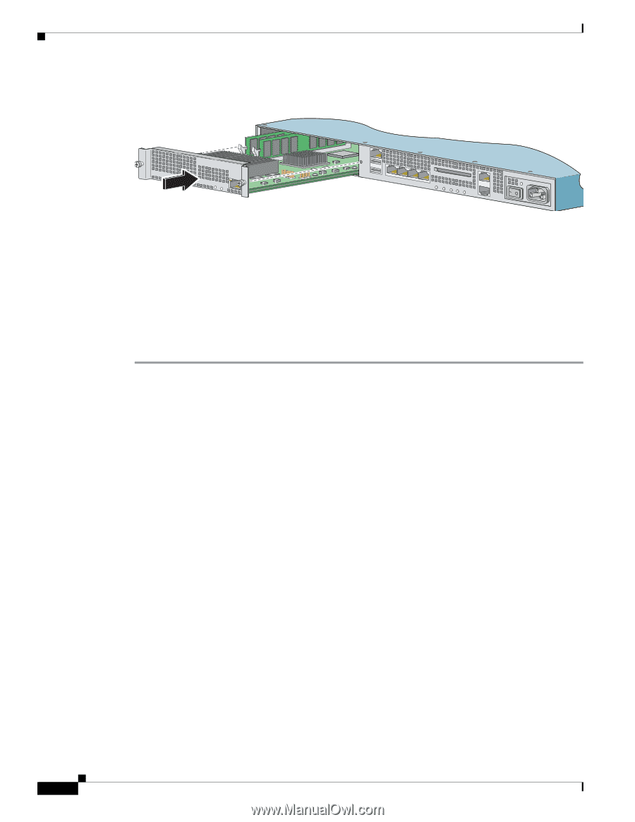
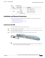
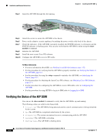
Installation and Removal Instructions Step 4 Insert the AIP SSM through the slot opening. Chapter 6 Installing the AIP SSM MGMT USB2 USB1 SPEED PWR STATUS LINK/ACT LINK 3 SPD LINK 2 SPD LINK 1 SPD LINK 0 SPD FLASH POWER STATUS ACTIVE VPN FLASH Step 5 Step 6 Step 7 Step 8 Step 9 Step 10 Attach the screws to secure the AIP SSM to the chassis. Power on the adaptive security appliance by pushing the power switch at the back of the chassis. Check the indicators. If the AIP SSM is properly installed, the POWER indicator is solid green and the STATUS indicator is flashing green. You can also verify that the AIP SSM is online using the show module 1 command. Initialize the AIP SSM. Install the most recent Cisco IPS software. Configure the AIP SSM to receive IPS traffic. For More Information • For more information about ESD, see Working in an ESD Environment, page 1-32. • For the procedure for verifying that the AIP SSM is properly installed, see Verifying the Status of the AIP SSM, page 6-4. • For the procedure for using the setup command to initialize the AIP SSM, see Initializing the Sensor, page 10-1. • For the procedure for obtaining the latest Cisco IPS software, see Obtaining Cisco IPS Software, page 11-1. • For the procedure for configuring the AIP SSM to receive IPS traffic, refer to Configuring the AIP SSM. • For the procedure for using HTTPS to log in to IDM, refer to Logging In to IDM. Verifying the Status of the AIP SSM You can use the show module 1 command to verify that the AIP SSM is up and running. The following values are valid for the Status field: • Initializing-The AIP SSM is being detected and the control communication is being initialized by the system. • Up-The AIP SSM has completed initialization by the system. • Unresponsive-The system encountered an error communicating with the AIP SSM. • Reloading-The AIP SSM is reloading. • Shutting Down-The AIP SSM is shutting down. Cisco Intrusion Prevention System Appliance and Module Installation Guide for IPS 7.0 6-4 OL-18504-01
-
 1
1 -
2
-
3
-
4
-
5
-
6
-
7
-
8
-
9
-
10
-
11
-
12
-
13
-
14
-
15
-
16
-
17
-
18
-
19
-
20
-
21
-
22
-
23
-
24
-
25
-
26
-
27
-
28
-
29
-
30
-
31
-
32
-
33
-
34
-
35
-
36
-
37
-
38
-
39
-
40
-
41
-
42
-
43
-
44
-
45
-
46
-
47
-
48
-
49
-
50
-
51
-
52
-
53
-
54
-
55
-
56
-
57
-
58
-
59
-
60
-
61
-
62
-
63
-
64
-
65
-
66
-
67
-
68
-
69
-
70
-
71
-
72
-
73
-
74
-
75
-
76
-
77
-
78
-
79
-
80
-
81
-
82
-
83
-
84
-
85
-
86
-
87
-
88
-
89
-
90
-
91
-
92
-
93
-
94
-
95
-
96
-
97
-
98
-
99
-
100
-
101
-
102
-
103
-
104
-
105
-
106
-
107
-
108
-
109
-
110
-
111
-
112
-
113
-
114
-
115
-
116
-
117
-
118
-
119
-
120
-
121
-
122
-
123
-
124
-
125
-
126
-
127
-
128
-
129
-
130
-
131
-
132
-
133
-
134
-
135
-
136
-
137
-
138
-
139
-
140
-
141
-
142
-
143
-
144
-
145
-
146
-
147
-
148
-
 149
149 -
 150
150 -
 151
151 -
 152
152 -
 153
153 -
 154
154 -
 155
155 -
 156
156 -
 157
157 -
 158
158 -
 159
159 -
160
-
161
-
162
-
163
-
164
-
165
-
166
-
167
-
168
-
169
-
170
-
171
-
172
-
173
-
174
-
175
-
176
-
177
-
178
-
179
-
180
-
181
-
182
-
183
-
184
-
185
-
186
-
187
-
188
-
189
-
190
-
191
-
192
-
193
-
194
-
195
-
196
-
197
-
198
-
199
-
200
-
201
-
202
-
203
-
204
-
205
-
206
-
207
-
208
-
209
-
210
-
211
-
212
-
213
-
214
-
215
-
216
-
217
-
218
-
219
-
220
-
221
-
222
-
223
-
224
-
225
-
226
-
227
-
228
-
229
-
230
-
231
-
232
-
233
-
234
-
235
-
236
-
237
-
238
-
239
-
240
-
241
-
242
-
243
-
244
-
245
-
246
-
247
-
248
-
249
-
250
-
251
-
252
-
253
-
254
-
255
-
256
-
257
-
258
-
259
-
260
-
261
-
262
-
263
-
264
-
265
-
266
-
267
-
268
-
269
-
270
-
271
-
272
-
273
-
274
-
275
-
276
-
277
-
278
-
279
-
280
-
281
-
282
-
283
-
284
-
285
-
286
-
287
-
288
-
289
-
290
-
291
-
292
-
293
-
294
-
295
-
296
-
297
-
298
-
299
-
300
-
301
-
302
-
303
-
304
-
305
-
306
-
307
-
308
-
309
-
310
-
311
-
312
-
313
-
314
-
315
-
316
-
317
-
318
-
319
-
320
-
321
-
322
-
323
-
324
-
325
-
326
-
327
-
328
-
329
-
330
-
331
-
332
-
333
-
334
-
335
-
336
-
337
-
338
-
339
-
340
-
341
-
342
-
343
-
344
-
345
-
346
-
347
-
348
-
349
-
350
-
351
-
352
-
353
-
354
-
355
-
356
-
357
-
358
-
359
-
360
-
361
-
362
-
363
-
364
-
365
-
366
-
367
-
368
-
369
-
370
-
371
-
372
-
373
-
374
-
375
-
376
-
377
-
378
-
379
-
380
-
381
-
382
-
383
-
384
-
385
-
386
-
387
-
388
-
389
-
390
-
391
-
392
-
393
-
394
-
395
-
396
-
397
-
398
-
399
-
400
-
401
-
402
-
403
-
404
-
405
-
406
-
407
-
408
-
409
-
410
-
411
-
412
 |
 |