Cisco IPS-4255-K9 Installation Guide - Page 70
Supported Interface Cards
 |
UPC - 746320951096
View all Cisco IPS-4255-K9 manuals
Add to My Manuals
Save this manual to your list of manuals |
Page 70 highlights
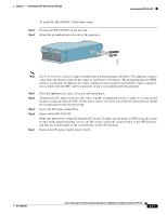
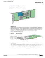
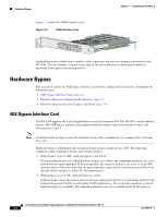
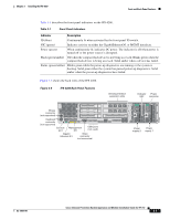
Supported Interface Cards Chapter 3 Installing the IPS 4260 The IPS 4260 has two built-in Gigabit Ethernet network ports and six expansion slots. The network port numbers increase from right to left and the expansion slot numbers increase from bottom to top and from right to left as shown in Figure 3-5 on page 3-7. Slots 2 and 3 are PCI-Express connectors and the other expansion slots are PCI-X slots. Slots 1 through 3 are full-height slots and slots 4 though 6 are half-height slots. The built-in management port is called Management0/0 and the built-in sensing interface is Gigabit-Ethernet0/1. Note Only expansion slots 2 and 3 are supported at this time. For improved reliability, the IPS 4260 uses a flash device for storage rather than a hard-disk drive. The IPS 4260 supports two optional network interface cards, the 2SX Fiber card, and the 4GE bypass interface card that contains the hardware-bypass feature. Initially the IPS 4260 supports only the built-in interfaces and these two interface cards. The IPS 4260 monitors greater than 1 Gbps of aggregate network traffic on multiple sensing interfaces and is also inline ready. It supports both copper and fiber interfaces. The 1-Gbps performance is traffic combined from all sensing interfaces. The 1-Gbps performance for the IPS 4260 is based on the following conditions: • 10,000 new TCP connections per second • 100,000 HTTP transactions per second • Average packet size of 450 bytes • System running IPS 6.0 software The IPS 4260 ships with one power supply, but it supports redundant power supplies. The IPS 4260 operates in load-sharing mode when the optional redundant power supply is installed. For More Information • For more information on how to obtain instructions and BIOS files from the Cisco website, see Obtaining Cisco IPS Software, page 11-1. • For more information on sensor interfaces, see Sensor Interfaces, page 1-4. • For more information on the 4GE bypass interface card, see Hardware Bypass, page 3-4. • For more information on installing and removing the power supply, see Installing and Removing the Power Supply, page 3-22. Supported Interface Cards The IPS 4260 supports three interface cards: the 4GE bypass interface card, the 2SX interface card, and the 10GE interface card. 4GE Bypass Interface Card The 4GE bypass interface card (part numbers IPS-4GE-BP-INT and IPS-4GE-BP-INT=) provides four 10/100/1000BASE-T (4GE) monitoring interfaces. The IPS 4260 supports up to two 4GE bypass interfaces cards for a total of eight GE bypass interfaces. The 4GE bypass interface card supports hardware bypass. Cisco Intrusion Prevention System Appliance and Module Installation Guide for IPS 7.0 3-2 OL-18504-01
-
 1
1 -
2
-
3
-
4
-
5
-
6
-
7
-
8
-
9
-
10
-
11
-
12
-
13
-
14
-
15
-
16
-
17
-
18
-
19
-
20
-
21
-
22
-
23
-
24
-
25
-
26
-
27
-
28
-
29
-
30
-
31
-
32
-
33
-
34
-
35
-
36
-
37
-
38
-
39
-
40
-
41
-
42
-
43
-
44
-
45
-
46
-
47
-
48
-
49
-
50
-
51
-
52
-
53
-
54
-
55
-
56
-
57
-
58
-
59
-
60
-
61
-
62
-
63
-
64
-
 65
65 -
 66
66 -
 67
67 -
 68
68 -
 69
69 -
 70
70 -
 71
71 -
 72
72 -
 73
73 -
 74
74 -
 75
75 -
76
-
77
-
78
-
79
-
80
-
81
-
82
-
83
-
84
-
85
-
86
-
87
-
88
-
89
-
90
-
91
-
92
-
93
-
94
-
95
-
96
-
97
-
98
-
99
-
100
-
101
-
102
-
103
-
104
-
105
-
106
-
107
-
108
-
109
-
110
-
111
-
112
-
113
-
114
-
115
-
116
-
117
-
118
-
119
-
120
-
121
-
122
-
123
-
124
-
125
-
126
-
127
-
128
-
129
-
130
-
131
-
132
-
133
-
134
-
135
-
136
-
137
-
138
-
139
-
140
-
141
-
142
-
143
-
144
-
145
-
146
-
147
-
148
-
149
-
150
-
151
-
152
-
153
-
154
-
155
-
156
-
157
-
158
-
159
-
160
-
161
-
162
-
163
-
164
-
165
-
166
-
167
-
168
-
169
-
170
-
171
-
172
-
173
-
174
-
175
-
176
-
177
-
178
-
179
-
180
-
181
-
182
-
183
-
184
-
185
-
186
-
187
-
188
-
189
-
190
-
191
-
192
-
193
-
194
-
195
-
196
-
197
-
198
-
199
-
200
-
201
-
202
-
203
-
204
-
205
-
206
-
207
-
208
-
209
-
210
-
211
-
212
-
213
-
214
-
215
-
216
-
217
-
218
-
219
-
220
-
221
-
222
-
223
-
224
-
225
-
226
-
227
-
228
-
229
-
230
-
231
-
232
-
233
-
234
-
235
-
236
-
237
-
238
-
239
-
240
-
241
-
242
-
243
-
244
-
245
-
246
-
247
-
248
-
249
-
250
-
251
-
252
-
253
-
254
-
255
-
256
-
257
-
258
-
259
-
260
-
261
-
262
-
263
-
264
-
265
-
266
-
267
-
268
-
269
-
270
-
271
-
272
-
273
-
274
-
275
-
276
-
277
-
278
-
279
-
280
-
281
-
282
-
283
-
284
-
285
-
286
-
287
-
288
-
289
-
290
-
291
-
292
-
293
-
294
-
295
-
296
-
297
-
298
-
299
-
300
-
301
-
302
-
303
-
304
-
305
-
306
-
307
-
308
-
309
-
310
-
311
-
312
-
313
-
314
-
315
-
316
-
317
-
318
-
319
-
320
-
321
-
322
-
323
-
324
-
325
-
326
-
327
-
328
-
329
-
330
-
331
-
332
-
333
-
334
-
335
-
336
-
337
-
338
-
339
-
340
-
341
-
342
-
343
-
344
-
345
-
346
-
347
-
348
-
349
-
350
-
351
-
352
-
353
-
354
-
355
-
356
-
357
-
358
-
359
-
360
-
361
-
362
-
363
-
364
-
365
-
366
-
367
-
368
-
369
-
370
-
371
-
372
-
373
-
374
-
375
-
376
-
377
-
378
-
379
-
380
-
381
-
382
-
383
-
384
-
385
-
386
-
387
-
388
-
389
-
390
-
391
-
392
-
393
-
394
-
395
-
396
-
397
-
398
-
399
-
400
-
401
-
402
-
403
-
404
-
405
-
406
-
407
-
408
-
409
-
410
-
411
-
412
 |
 |