Cisco IPS-4255-K9 Installation Guide - Page 311
Unable to See Alerts
 |
UPC - 746320951096
View all Cisco IPS-4255-K9 manuals
Add to My Manuals
Save this manual to your list of manuals |
Page 311 highlights
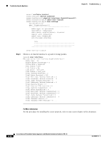
Chapter A Troubleshooting Troubleshooting the Appliance Step 3 Step 4 Step 5 Media Type = TX Link Status = Up Link Speed = Auto_100 Link Duplex = Auto_Full Total Packets Received = 1830137 Total Bytes Received = 131624465 Total Multicast Packets Received = 20 Total Receive Errors = 0 Total Receive FIFO Overruns = 0 Total Packets Transmitted = 220052 Total Bytes Transmitted = 103796666 Total Transmit Errors = 0 Total Transmit FIFO Overruns = 0 sensor# If the Link Status is down, make sure the sensing port is connected properly. a. Make sure the sensing port is connected properly on the appliance. b. Make sure the sensing port is connected to the correct SPAN or VACL capture port on the IDSM2. Verify the interface configuration. a. Make sure you have the interfaces configured properly. b. Verify the SPAN and VACL capture port configuration on the Cisco switch. Refer to your switch documentation for the procedure. Verify again that the interfaces are up and that the packet count is increasing. sensor# show interfaces For More Information • For the procedure for properly installing the sensing interface on your sensor, refer to the chapter on your appliance in this document. • For the procedure for connecting SPAN and VACL capture ports on the IDSM2, refer to Configuring the IDSM2. • For the procedures for configuring interfaces on your sensor, refer to Configuring Interfaces. Unable to See Alerts If you are not seeing alerts, try the following: • Make sure the signature is enabled • Make sure the signature is not retired • Make sure that you have Produce Alert configured as an action Note If you choose Produce Alert, but come back later and add another event action and do not add Produce Alert to the new configuration, alerts are not sent to the Event Store. Every time you configure a signature, the new configuration overwrites the old one, so make sure you have configured all the event actions you want for each signature. • Make sure the sensor is seeing packets OL-18504-01 Cisco Intrusion Prevention System Appliance and Module Installation Guide for IPS 7.0 A-33
-
 1
1 -
2
-
3
-
4
-
5
-
6
-
7
-
8
-
9
-
10
-
11
-
12
-
13
-
14
-
15
-
16
-
17
-
18
-
19
-
20
-
21
-
22
-
23
-
24
-
25
-
26
-
27
-
28
-
29
-
30
-
31
-
32
-
33
-
34
-
35
-
36
-
37
-
38
-
39
-
40
-
41
-
42
-
43
-
44
-
45
-
46
-
47
-
48
-
49
-
50
-
51
-
52
-
53
-
54
-
55
-
56
-
57
-
58
-
59
-
60
-
61
-
62
-
63
-
64
-
65
-
66
-
67
-
68
-
69
-
70
-
71
-
72
-
73
-
74
-
75
-
76
-
77
-
78
-
79
-
80
-
81
-
82
-
83
-
84
-
85
-
86
-
87
-
88
-
89
-
90
-
91
-
92
-
93
-
94
-
95
-
96
-
97
-
98
-
99
-
100
-
101
-
102
-
103
-
104
-
105
-
106
-
107
-
108
-
109
-
110
-
111
-
112
-
113
-
114
-
115
-
116
-
117
-
118
-
119
-
120
-
121
-
122
-
123
-
124
-
125
-
126
-
127
-
128
-
129
-
130
-
131
-
132
-
133
-
134
-
135
-
136
-
137
-
138
-
139
-
140
-
141
-
142
-
143
-
144
-
145
-
146
-
147
-
148
-
149
-
150
-
151
-
152
-
153
-
154
-
155
-
156
-
157
-
158
-
159
-
160
-
161
-
162
-
163
-
164
-
165
-
166
-
167
-
168
-
169
-
170
-
171
-
172
-
173
-
174
-
175
-
176
-
177
-
178
-
179
-
180
-
181
-
182
-
183
-
184
-
185
-
186
-
187
-
188
-
189
-
190
-
191
-
192
-
193
-
194
-
195
-
196
-
197
-
198
-
199
-
200
-
201
-
202
-
203
-
204
-
205
-
206
-
207
-
208
-
209
-
210
-
211
-
212
-
213
-
214
-
215
-
216
-
217
-
218
-
219
-
220
-
221
-
222
-
223
-
224
-
225
-
226
-
227
-
228
-
229
-
230
-
231
-
232
-
233
-
234
-
235
-
236
-
237
-
238
-
239
-
240
-
241
-
242
-
243
-
244
-
245
-
246
-
247
-
248
-
249
-
250
-
251
-
252
-
253
-
254
-
255
-
256
-
257
-
258
-
259
-
260
-
261
-
262
-
263
-
264
-
265
-
266
-
267
-
268
-
269
-
270
-
271
-
272
-
273
-
274
-
275
-
276
-
277
-
278
-
279
-
280
-
281
-
282
-
283
-
284
-
285
-
286
-
287
-
288
-
289
-
290
-
291
-
292
-
293
-
294
-
295
-
296
-
297
-
298
-
299
-
300
-
301
-
302
-
303
-
304
-
305
-
 306
306 -
 307
307 -
 308
308 -
 309
309 -
 310
310 -
 311
311 -
 312
312 -
 313
313 -
 314
314 -
 315
315 -
 316
316 -
317
-
318
-
319
-
320
-
321
-
322
-
323
-
324
-
325
-
326
-
327
-
328
-
329
-
330
-
331
-
332
-
333
-
334
-
335
-
336
-
337
-
338
-
339
-
340
-
341
-
342
-
343
-
344
-
345
-
346
-
347
-
348
-
349
-
350
-
351
-
352
-
353
-
354
-
355
-
356
-
357
-
358
-
359
-
360
-
361
-
362
-
363
-
364
-
365
-
366
-
367
-
368
-
369
-
370
-
371
-
372
-
373
-
374
-
375
-
376
-
377
-
378
-
379
-
380
-
381
-
382
-
383
-
384
-
385
-
386
-
387
-
388
-
389
-
390
-
391
-
392
-
393
-
394
-
395
-
396
-
397
-
398
-
399
-
400
-
401
-
402
-
403
-
404
-
405
-
406
-
407
-
408
-
409
-
410
-
411
-
412
 |
 |