Cisco IPS-4255-K9 Installation Guide - Page 159
Using the TCP Reset Interface, Front Panel Features
 |
UPC - 746320951096
View all Cisco IPS-4255-K9 manuals
Add to My Manuals
Save this manual to your list of manuals |
Page 159 highlights
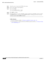
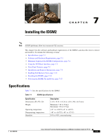
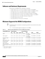
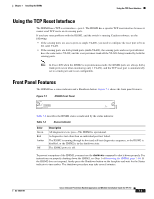
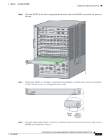
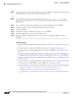
Chapter 7 Installing the IDSM2 Using the TCP Reset Interface Using the TCP Reset Interface The IDSM2 has a TCP reset interface-port 1. The IDSM2 has a specific TCP reset interface because it cannot send TCP resets on its sensing ports. If you have reset problems with the IDSM2, and the switch is running Catalyst software, try the following: • If the sensing ports are access ports (a single VLAN), you need to configure the reset port to be in the same VLAN. • If the sensing ports are dot1q trunk ports (multi-VLAN), the sensing ports and reset port all must have the same native VLAN, and the reset port must trunk all the VLANs being trunked by both the sensing ports. Note In Cisco IOS when the IDSM2 is in promiscuous mode, the IDSM2 ports are always dot1q trunk ports (even when monitoring only 1 VLAN), and the TCP reset port is automatically set to a trunk port and is not configurable. Front Panel Features The IDSM2 has a status indicator and a Shutdown button. Figure 7-1 shows the front panel features. Figure 7-1 WS-SVC-IDSM2 STATUS INTRUSION DETECTION MODULE IDSM2 Front Panel SHUTDOWN 83832 Table 7-3 describes the IDSM2 states as indicated by the status indicator. Table 7-3 Status Indicator Color Green Red Amber Off Description All diagnostics tests pass-The IDSM2 is operational. A diagnostics test other than an individual port test failed. The IDSM2 is running through its boot and self-test diagnostics sequence, or the IDSM2 is disabled, or the IDSM2 is in the shutdown state. The IDSM2 power is off. To prevent corruption of the IDSM2, you must use the shutdown command to shut it down properly. For instructions on properly shutting down the IDSM2, see Step 1 of Removing the IDSM2, page 7-10. If the IDSM2 does not respond, firmly press the Shutdown button on the faceplate and wait for the Status indicator to turn amber. The shutdown procedure may take several minutes. OL-18504-01 Cisco Intrusion Prevention System Appliance and Module Installation Guide for IPS 7.0 7-3
-
 1
1 -
2
-
3
-
4
-
5
-
6
-
7
-
8
-
9
-
10
-
11
-
12
-
13
-
14
-
15
-
16
-
17
-
18
-
19
-
20
-
21
-
22
-
23
-
24
-
25
-
26
-
27
-
28
-
29
-
30
-
31
-
32
-
33
-
34
-
35
-
36
-
37
-
38
-
39
-
40
-
41
-
42
-
43
-
44
-
45
-
46
-
47
-
48
-
49
-
50
-
51
-
52
-
53
-
54
-
55
-
56
-
57
-
58
-
59
-
60
-
61
-
62
-
63
-
64
-
65
-
66
-
67
-
68
-
69
-
70
-
71
-
72
-
73
-
74
-
75
-
76
-
77
-
78
-
79
-
80
-
81
-
82
-
83
-
84
-
85
-
86
-
87
-
88
-
89
-
90
-
91
-
92
-
93
-
94
-
95
-
96
-
97
-
98
-
99
-
100
-
101
-
102
-
103
-
104
-
105
-
106
-
107
-
108
-
109
-
110
-
111
-
112
-
113
-
114
-
115
-
116
-
117
-
118
-
119
-
120
-
121
-
122
-
123
-
124
-
125
-
126
-
127
-
128
-
129
-
130
-
131
-
132
-
133
-
134
-
135
-
136
-
137
-
138
-
139
-
140
-
141
-
142
-
143
-
144
-
145
-
146
-
147
-
148
-
149
-
150
-
151
-
152
-
153
-
 154
154 -
 155
155 -
 156
156 -
 157
157 -
 158
158 -
 159
159 -
 160
160 -
 161
161 -
 162
162 -
 163
163 -
 164
164 -
165
-
166
-
167
-
168
-
169
-
170
-
171
-
172
-
173
-
174
-
175
-
176
-
177
-
178
-
179
-
180
-
181
-
182
-
183
-
184
-
185
-
186
-
187
-
188
-
189
-
190
-
191
-
192
-
193
-
194
-
195
-
196
-
197
-
198
-
199
-
200
-
201
-
202
-
203
-
204
-
205
-
206
-
207
-
208
-
209
-
210
-
211
-
212
-
213
-
214
-
215
-
216
-
217
-
218
-
219
-
220
-
221
-
222
-
223
-
224
-
225
-
226
-
227
-
228
-
229
-
230
-
231
-
232
-
233
-
234
-
235
-
236
-
237
-
238
-
239
-
240
-
241
-
242
-
243
-
244
-
245
-
246
-
247
-
248
-
249
-
250
-
251
-
252
-
253
-
254
-
255
-
256
-
257
-
258
-
259
-
260
-
261
-
262
-
263
-
264
-
265
-
266
-
267
-
268
-
269
-
270
-
271
-
272
-
273
-
274
-
275
-
276
-
277
-
278
-
279
-
280
-
281
-
282
-
283
-
284
-
285
-
286
-
287
-
288
-
289
-
290
-
291
-
292
-
293
-
294
-
295
-
296
-
297
-
298
-
299
-
300
-
301
-
302
-
303
-
304
-
305
-
306
-
307
-
308
-
309
-
310
-
311
-
312
-
313
-
314
-
315
-
316
-
317
-
318
-
319
-
320
-
321
-
322
-
323
-
324
-
325
-
326
-
327
-
328
-
329
-
330
-
331
-
332
-
333
-
334
-
335
-
336
-
337
-
338
-
339
-
340
-
341
-
342
-
343
-
344
-
345
-
346
-
347
-
348
-
349
-
350
-
351
-
352
-
353
-
354
-
355
-
356
-
357
-
358
-
359
-
360
-
361
-
362
-
363
-
364
-
365
-
366
-
367
-
368
-
369
-
370
-
371
-
372
-
373
-
374
-
375
-
376
-
377
-
378
-
379
-
380
-
381
-
382
-
383
-
384
-
385
-
386
-
387
-
388
-
389
-
390
-
391
-
392
-
393
-
394
-
395
-
396
-
397
-
398
-
399
-
400
-
401
-
402
-
403
-
404
-
405
-
406
-
407
-
408
-
409
-
410
-
411
-
412
 |
 |