Cisco IPS-4255-K9 Installation Guide - Page 194
Basic Sensor Setup
 |
UPC - 746320951096
View all Cisco IPS-4255-K9 manuals
Add to My Manuals
Save this manual to your list of manuals |
Page 194 highlights
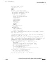
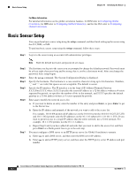
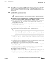
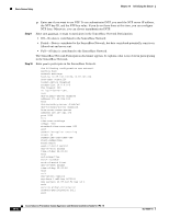
Basic Sensor Setup Chapter 10 Initializing the Sensor For More Information For detailed information on the global correlation features, for IDM refer to Configuring Global Correlation, for IME refer to Configuring Global Correlation, and for the CLI, refer to Configuring Global Correlation. Basic Sensor Setup You can perform basic sensor setup using the setup command, and then finish setting up the sensor using the CLI, IDM, or IME. To perform basic sensor setup using the setup command, follow these steps: Step 1 Log in to the sensor using an account with administrator privileges. Note Both the default username and password are cisco. Step 2 Step 3 Step 4 Step 5 Step 6 Step 7 The first time you log in to the sensor you are prompted to change the default password. Passwords must be at least eight characters long and be strong, that is, not be a dictionary word. After you change the password, basic setup begins. Enter the setup command. The System Configuration Dialog is displayed. Specify the hostname. The hostname is a case-sensitive character string up to 64 characters. Numbers, "_" and "-" are valid, but spaces are not acceptable. The default is sensor. Specify the IP interface. The IP interface is in the form of IP Address/Netmask,Gateway: X.X.X.X/nn,Y.Y.Y.Y, where X.X.X.X specifies the sensor IP address as a 32-bit address written as 4 octets separated by periods, nn specifies the number of bits in the netmask, and Y.Y.Y.Y specifies the default gateway as a 32-bit address written as 4 octets separated by periods. Enter yes to modify the network access list. a. If you want to delete an entry, enter the number of the entry and press Enter, or press Enter to get to the Permit line. b. Enter the IP address and netmask of the network you want to add to the access list. For example, 10.0.0.0/8 permits all IP addresses on the 10.0.0.0 network (10.0.0.0-10.255.255.255) and 10.1.1.0/24 permits only the IP addresses on the 10.1.1.0 subnet (10.1.1.0-10.1.1.255). If you want to permit access to a single IP address than the entire network, use a 32-bit netmask. For example, 10.1.1.1/32 permits just the 10.1.1.1 address. c. Repeat Step b until you have added all networks that you want to add to the access list, and then press Enter at a blank permit line to go to the next step. You must configure a DNS server or an HTTP proxy server for Global Correlation to operate. a. Enter yes to add a DNS server, and then enter the DNS server IP address. b. Enter yes to add an HTTP proxy server, and then enter the HTTP proxy server IP address and port number. 10-4 Cisco Intrusion Prevention System Appliance and Module Installation Guide for IPS 7.0 OL-18504-01
-
 1
1 -
2
-
3
-
4
-
5
-
6
-
7
-
8
-
9
-
10
-
11
-
12
-
13
-
14
-
15
-
16
-
17
-
18
-
19
-
20
-
21
-
22
-
23
-
24
-
25
-
26
-
27
-
28
-
29
-
30
-
31
-
32
-
33
-
34
-
35
-
36
-
37
-
38
-
39
-
40
-
41
-
42
-
43
-
44
-
45
-
46
-
47
-
48
-
49
-
50
-
51
-
52
-
53
-
54
-
55
-
56
-
57
-
58
-
59
-
60
-
61
-
62
-
63
-
64
-
65
-
66
-
67
-
68
-
69
-
70
-
71
-
72
-
73
-
74
-
75
-
76
-
77
-
78
-
79
-
80
-
81
-
82
-
83
-
84
-
85
-
86
-
87
-
88
-
89
-
90
-
91
-
92
-
93
-
94
-
95
-
96
-
97
-
98
-
99
-
100
-
101
-
102
-
103
-
104
-
105
-
106
-
107
-
108
-
109
-
110
-
111
-
112
-
113
-
114
-
115
-
116
-
117
-
118
-
119
-
120
-
121
-
122
-
123
-
124
-
125
-
126
-
127
-
128
-
129
-
130
-
131
-
132
-
133
-
134
-
135
-
136
-
137
-
138
-
139
-
140
-
141
-
142
-
143
-
144
-
145
-
146
-
147
-
148
-
149
-
150
-
151
-
152
-
153
-
154
-
155
-
156
-
157
-
158
-
159
-
160
-
161
-
162
-
163
-
164
-
165
-
166
-
167
-
168
-
169
-
170
-
171
-
172
-
173
-
174
-
175
-
176
-
177
-
178
-
179
-
180
-
181
-
182
-
183
-
184
-
185
-
186
-
187
-
188
-
 189
189 -
 190
190 -
 191
191 -
 192
192 -
 193
193 -
 194
194 -
 195
195 -
 196
196 -
 197
197 -
 198
198 -
 199
199 -
200
-
201
-
202
-
203
-
204
-
205
-
206
-
207
-
208
-
209
-
210
-
211
-
212
-
213
-
214
-
215
-
216
-
217
-
218
-
219
-
220
-
221
-
222
-
223
-
224
-
225
-
226
-
227
-
228
-
229
-
230
-
231
-
232
-
233
-
234
-
235
-
236
-
237
-
238
-
239
-
240
-
241
-
242
-
243
-
244
-
245
-
246
-
247
-
248
-
249
-
250
-
251
-
252
-
253
-
254
-
255
-
256
-
257
-
258
-
259
-
260
-
261
-
262
-
263
-
264
-
265
-
266
-
267
-
268
-
269
-
270
-
271
-
272
-
273
-
274
-
275
-
276
-
277
-
278
-
279
-
280
-
281
-
282
-
283
-
284
-
285
-
286
-
287
-
288
-
289
-
290
-
291
-
292
-
293
-
294
-
295
-
296
-
297
-
298
-
299
-
300
-
301
-
302
-
303
-
304
-
305
-
306
-
307
-
308
-
309
-
310
-
311
-
312
-
313
-
314
-
315
-
316
-
317
-
318
-
319
-
320
-
321
-
322
-
323
-
324
-
325
-
326
-
327
-
328
-
329
-
330
-
331
-
332
-
333
-
334
-
335
-
336
-
337
-
338
-
339
-
340
-
341
-
342
-
343
-
344
-
345
-
346
-
347
-
348
-
349
-
350
-
351
-
352
-
353
-
354
-
355
-
356
-
357
-
358
-
359
-
360
-
361
-
362
-
363
-
364
-
365
-
366
-
367
-
368
-
369
-
370
-
371
-
372
-
373
-
374
-
375
-
376
-
377
-
378
-
379
-
380
-
381
-
382
-
383
-
384
-
385
-
386
-
387
-
388
-
389
-
390
-
391
-
392
-
393
-
394
-
395
-
396
-
397
-
398
-
399
-
400
-
401
-
402
-
403
-
404
-
405
-
406
-
407
-
408
-
409
-
410
-
411
-
412
 |
 |