Cisco IPS-4255-K9 Installation Guide - Page 28
Interface Restrictions, Designating the Alternate TCP Reset Interface
 |
UPC - 746320951096
View all Cisco IPS-4255-K9 manuals
Add to My Manuals
Save this manual to your list of manuals |
Page 28 highlights
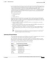
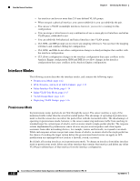
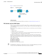
How the Sensor Functions Chapter 1 Introducing the Sensor Table 1-3 Alternate TCP Reset Interfaces (continued) Sensor Alternate TCP Reset Interface IPS 4260 Any sensing interface IPS 4270-20 Any sensing interface NME IPS None 1. This is an internal interface on the Catalyst backplane. Designating the Alternate TCP Reset Interface You need to designate an alternate TCP reset interface in the following situations: • When a switch is being monitored with either SPAN or VACL capture and the switch does not accept incoming packets on the SPAN or VACL capture port. • When a switch is being monitored with either SPAN or VACL capture for multiple VLANs, and the switch does not accept incoming packets with 802.1q headers. Note The TCP resets need 802.1q headers to tell which VLAN the resets should be sent on. • When a network tap is used for monitoring a connection. Note Taps do not permit incoming traffic from the sensor. You can only assign a sensing interface as an alternate TCP reset interface. You cannot configure the management interface as an alternate TCP reset interface. Interface Restrictions The following restrictions apply to configuring interfaces on the sensor: • Physical Interfaces - On modules (AIM IPS, AIP SSM, IDSM2, and NME IPS), all backplane interfaces have fixed speed, duplex, and state settings. These settings are protected in the default configuration on all backplane interfaces. - For nonbackplane FastEthernet interfaces the valid speed settings are 10 Mbps, 100 Mbps, and auto. Valid duplex settings are full, half, and auto. - For Gigabit copper interfaces (1000-TX on the IPS 4240, IPS 4255, IPS 4260, and IPS 4270-20), valid speed settings are 10 Mbps, 100 Mbps, 1000 Mbps, and auto. Valid duplex settings are full, half, and auto. - For Gigabit (copper or fiber) interfaces, if the speed is configured for 1000 Mbps, the only valid duplex setting is auto. - The command and control interface cannot also serve as a sensing interface. 1-10 Cisco Intrusion Prevention System Appliance and Module Installation Guide for IPS 7.0 OL-18504-01
-
 1
1 -
2
-
3
-
4
-
5
-
6
-
7
-
8
-
9
-
10
-
11
-
12
-
13
-
14
-
15
-
16
-
17
-
18
-
19
-
20
-
21
-
22
-
 23
23 -
 24
24 -
 25
25 -
 26
26 -
 27
27 -
 28
28 -
 29
29 -
 30
30 -
 31
31 -
 32
32 -
 33
33 -
34
-
35
-
36
-
37
-
38
-
39
-
40
-
41
-
42
-
43
-
44
-
45
-
46
-
47
-
48
-
49
-
50
-
51
-
52
-
53
-
54
-
55
-
56
-
57
-
58
-
59
-
60
-
61
-
62
-
63
-
64
-
65
-
66
-
67
-
68
-
69
-
70
-
71
-
72
-
73
-
74
-
75
-
76
-
77
-
78
-
79
-
80
-
81
-
82
-
83
-
84
-
85
-
86
-
87
-
88
-
89
-
90
-
91
-
92
-
93
-
94
-
95
-
96
-
97
-
98
-
99
-
100
-
101
-
102
-
103
-
104
-
105
-
106
-
107
-
108
-
109
-
110
-
111
-
112
-
113
-
114
-
115
-
116
-
117
-
118
-
119
-
120
-
121
-
122
-
123
-
124
-
125
-
126
-
127
-
128
-
129
-
130
-
131
-
132
-
133
-
134
-
135
-
136
-
137
-
138
-
139
-
140
-
141
-
142
-
143
-
144
-
145
-
146
-
147
-
148
-
149
-
150
-
151
-
152
-
153
-
154
-
155
-
156
-
157
-
158
-
159
-
160
-
161
-
162
-
163
-
164
-
165
-
166
-
167
-
168
-
169
-
170
-
171
-
172
-
173
-
174
-
175
-
176
-
177
-
178
-
179
-
180
-
181
-
182
-
183
-
184
-
185
-
186
-
187
-
188
-
189
-
190
-
191
-
192
-
193
-
194
-
195
-
196
-
197
-
198
-
199
-
200
-
201
-
202
-
203
-
204
-
205
-
206
-
207
-
208
-
209
-
210
-
211
-
212
-
213
-
214
-
215
-
216
-
217
-
218
-
219
-
220
-
221
-
222
-
223
-
224
-
225
-
226
-
227
-
228
-
229
-
230
-
231
-
232
-
233
-
234
-
235
-
236
-
237
-
238
-
239
-
240
-
241
-
242
-
243
-
244
-
245
-
246
-
247
-
248
-
249
-
250
-
251
-
252
-
253
-
254
-
255
-
256
-
257
-
258
-
259
-
260
-
261
-
262
-
263
-
264
-
265
-
266
-
267
-
268
-
269
-
270
-
271
-
272
-
273
-
274
-
275
-
276
-
277
-
278
-
279
-
280
-
281
-
282
-
283
-
284
-
285
-
286
-
287
-
288
-
289
-
290
-
291
-
292
-
293
-
294
-
295
-
296
-
297
-
298
-
299
-
300
-
301
-
302
-
303
-
304
-
305
-
306
-
307
-
308
-
309
-
310
-
311
-
312
-
313
-
314
-
315
-
316
-
317
-
318
-
319
-
320
-
321
-
322
-
323
-
324
-
325
-
326
-
327
-
328
-
329
-
330
-
331
-
332
-
333
-
334
-
335
-
336
-
337
-
338
-
339
-
340
-
341
-
342
-
343
-
344
-
345
-
346
-
347
-
348
-
349
-
350
-
351
-
352
-
353
-
354
-
355
-
356
-
357
-
358
-
359
-
360
-
361
-
362
-
363
-
364
-
365
-
366
-
367
-
368
-
369
-
370
-
371
-
372
-
373
-
374
-
375
-
376
-
377
-
378
-
379
-
380
-
381
-
382
-
383
-
384
-
385
-
386
-
387
-
388
-
389
-
390
-
391
-
392
-
393
-
394
-
395
-
396
-
397
-
398
-
399
-
400
-
401
-
402
-
403
-
404
-
405
-
406
-
407
-
408
-
409
-
410
-
411
-
412
 |
 |