Cisco IPS-4255-K9 Installation Guide - Page 23
Command and Control Interface, Sensor
 |
UPC - 746320951096
View all Cisco IPS-4255-K9 manuals
Add to My Manuals
Save this manual to your list of manuals |
Page 23 highlights
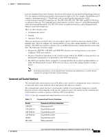
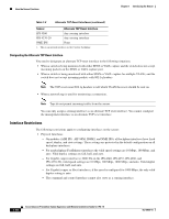
Chapter 1 Introducing the Sensor How the Sensor Functions ports are numbered from top to bottom). Interfaces with a given slot are numbered beginning with port 0 for the right port with the port numbers increasing from right to left. For example, GigabitEthernet2/1 supports a maximum speed of 1 Gigabit and is the second-from-the-right interface in the second-from-the bottom PCI expansion slot. The IPS 4240, IPS 4255, IPS 4260, and IPS 4270-20 are exceptions to this rule. The command and control interface on these sensors is called Management0/0 rather than GigabitEthernet0/0. The IPS 4270-20 has an additional interface called Management0/1, which is reserved for future use. There are three interface roles: • Command and control • Sensing • Alternate TCP reset There are restrictions on which roles you can assign to specific interfaces and some interfaces have multiple roles. You can configure any sensing interface to any other sensing interface as its TCP reset interface. The TCP reset interface can also serve as an IDS (promiscuous) sensing interface at the same time. The following restrictions apply: • Because the AIM IPS, AIP SSM, and NME IPS only have one sensing interface, you cannot configure a TCP reset interface. • Because of hardware limitations on the Catalyst switch, both of the IDSM2 sensing interfaces are permanently configured to use System0/1 as the TCP reset interface. • The TCP reset interface that is assigned to a sensing interface has no effect in inline interface or inline VLAN pair mode, because TCP resets are always sent on the sensing interfaces in those modes. Note Each physical interface can be divided into VLAN group subinterfaces, each of which consists of a group of VLANs on that interface. Command and Control Interface The command and control interface has an IP address and is used for configuring the sensor. It receives security and status events from the sensor and queries the sensor for statistics. The command and control interface is permanently enabled. It is permanently mapped to a specific physical interface, which depends on the specific model of sensor. You cannot use the command and control interface as either a sensing or alternate TCP reset interface. Table 1-1 lists the command and control interfaces for each sensor. Table 1-1 Command and Control Interfaces Sensor AIM IPS AIP SSM-10 AIP SSM-20 AIP SSM-40 IDSM2 IPS 4240 Command and Control Interface Management0/0 GigabitEthernet0/0 GigabitEthernet0/0 GigabitEthernet0/0 GigabitEthernet0/2 Management0/0 OL-18504-01 Cisco Intrusion Prevention System Appliance and Module Installation Guide for IPS 7.0 1-5
-
 1
1 -
2
-
3
-
4
-
5
-
6
-
7
-
8
-
9
-
10
-
11
-
12
-
13
-
14
-
15
-
16
-
17
-
 18
18 -
 19
19 -
 20
20 -
 21
21 -
 22
22 -
 23
23 -
 24
24 -
 25
25 -
 26
26 -
 27
27 -
 28
28 -
29
-
30
-
31
-
32
-
33
-
34
-
35
-
36
-
37
-
38
-
39
-
40
-
41
-
42
-
43
-
44
-
45
-
46
-
47
-
48
-
49
-
50
-
51
-
52
-
53
-
54
-
55
-
56
-
57
-
58
-
59
-
60
-
61
-
62
-
63
-
64
-
65
-
66
-
67
-
68
-
69
-
70
-
71
-
72
-
73
-
74
-
75
-
76
-
77
-
78
-
79
-
80
-
81
-
82
-
83
-
84
-
85
-
86
-
87
-
88
-
89
-
90
-
91
-
92
-
93
-
94
-
95
-
96
-
97
-
98
-
99
-
100
-
101
-
102
-
103
-
104
-
105
-
106
-
107
-
108
-
109
-
110
-
111
-
112
-
113
-
114
-
115
-
116
-
117
-
118
-
119
-
120
-
121
-
122
-
123
-
124
-
125
-
126
-
127
-
128
-
129
-
130
-
131
-
132
-
133
-
134
-
135
-
136
-
137
-
138
-
139
-
140
-
141
-
142
-
143
-
144
-
145
-
146
-
147
-
148
-
149
-
150
-
151
-
152
-
153
-
154
-
155
-
156
-
157
-
158
-
159
-
160
-
161
-
162
-
163
-
164
-
165
-
166
-
167
-
168
-
169
-
170
-
171
-
172
-
173
-
174
-
175
-
176
-
177
-
178
-
179
-
180
-
181
-
182
-
183
-
184
-
185
-
186
-
187
-
188
-
189
-
190
-
191
-
192
-
193
-
194
-
195
-
196
-
197
-
198
-
199
-
200
-
201
-
202
-
203
-
204
-
205
-
206
-
207
-
208
-
209
-
210
-
211
-
212
-
213
-
214
-
215
-
216
-
217
-
218
-
219
-
220
-
221
-
222
-
223
-
224
-
225
-
226
-
227
-
228
-
229
-
230
-
231
-
232
-
233
-
234
-
235
-
236
-
237
-
238
-
239
-
240
-
241
-
242
-
243
-
244
-
245
-
246
-
247
-
248
-
249
-
250
-
251
-
252
-
253
-
254
-
255
-
256
-
257
-
258
-
259
-
260
-
261
-
262
-
263
-
264
-
265
-
266
-
267
-
268
-
269
-
270
-
271
-
272
-
273
-
274
-
275
-
276
-
277
-
278
-
279
-
280
-
281
-
282
-
283
-
284
-
285
-
286
-
287
-
288
-
289
-
290
-
291
-
292
-
293
-
294
-
295
-
296
-
297
-
298
-
299
-
300
-
301
-
302
-
303
-
304
-
305
-
306
-
307
-
308
-
309
-
310
-
311
-
312
-
313
-
314
-
315
-
316
-
317
-
318
-
319
-
320
-
321
-
322
-
323
-
324
-
325
-
326
-
327
-
328
-
329
-
330
-
331
-
332
-
333
-
334
-
335
-
336
-
337
-
338
-
339
-
340
-
341
-
342
-
343
-
344
-
345
-
346
-
347
-
348
-
349
-
350
-
351
-
352
-
353
-
354
-
355
-
356
-
357
-
358
-
359
-
360
-
361
-
362
-
363
-
364
-
365
-
366
-
367
-
368
-
369
-
370
-
371
-
372
-
373
-
374
-
375
-
376
-
377
-
378
-
379
-
380
-
381
-
382
-
383
-
384
-
385
-
386
-
387
-
388
-
389
-
390
-
391
-
392
-
393
-
394
-
395
-
396
-
397
-
398
-
399
-
400
-
401
-
402
-
403
-
404
-
405
-
406
-
407
-
408
-
409
-
410
-
411
-
412
 |
 |