Cisco IPS-4255-K9 Installation Guide - Page 251
Installing the IPS 4240 and IPS 4255 System Images
 |
UPC - 746320951096
View all Cisco IPS-4255-K9 manuals
Add to My Manuals
Save this manual to your list of manuals |
Page 251 highlights
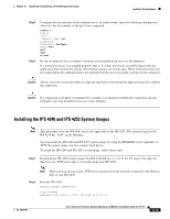
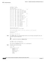
Chapter 12 Upgrading, Downgrading, and Installing System Images Installing System Images Step 2 Step 3 Configure the line and port on the terminal server. In enable mode, enter the following configuration, where # is the line number of the port to be configured. config t line # login transport input all stopbits 1 flowcontrol hardware speed 9600 exit exit wr mem Be sure to properly close a terminal session to avoid unauthorized access to the appliance. If a terminal session is not stopped properly, that is, if it does not receive an exit(0) signal from the application that initiated the session, the terminal session can remain open. When terminal sessions are not stopped properly, authentication is not performed on the next session that is opened on the serial port. Caution Always exit your session and return to a login prompt before terminating the application used to establish the connection. Caution If a connection is dropped or terminated by accident, you should reestablish the connection and exit normally to prevent unauthorized access to the appliance. Installing the IPS 4240 and IPS 4255 System Images Note This procedure is for the IPS 4240, but is also applicable to the IPS 4255. The system image for the IPS 4255 has "4255" in the filename. You can install the IPS 4240 and IPS 4255 system image by using the ROMMON on the appliance to TFTP the system image onto the compact flash device. To install the IPS 4240 and IPS 4255 system image, follow these steps: Step 1 Download the IPS 4240 system image file (IPS 4240-K9-sys-1.1-a-6.27.0-1-E3.img) to the tftp root directory of a TFTP server that is accessible from your IPS 4240. Note Make sure you can access the TFTP server location from the network connected to the Ethernet port of your IPS 4240. Step 2 Boot the IPS 4240. Booting system, please wait... CISCO SYSTEMS Embedded BIOS Version 1.0(5)0 09/14/04 12:23:35.90 OL-18504-01 Cisco Intrusion Prevention System Appliance and Module Installation Guide for IPS 7.0 12-15
-
 1
1 -
2
-
3
-
4
-
5
-
6
-
7
-
8
-
9
-
10
-
11
-
12
-
13
-
14
-
15
-
16
-
17
-
18
-
19
-
20
-
21
-
22
-
23
-
24
-
25
-
26
-
27
-
28
-
29
-
30
-
31
-
32
-
33
-
34
-
35
-
36
-
37
-
38
-
39
-
40
-
41
-
42
-
43
-
44
-
45
-
46
-
47
-
48
-
49
-
50
-
51
-
52
-
53
-
54
-
55
-
56
-
57
-
58
-
59
-
60
-
61
-
62
-
63
-
64
-
65
-
66
-
67
-
68
-
69
-
70
-
71
-
72
-
73
-
74
-
75
-
76
-
77
-
78
-
79
-
80
-
81
-
82
-
83
-
84
-
85
-
86
-
87
-
88
-
89
-
90
-
91
-
92
-
93
-
94
-
95
-
96
-
97
-
98
-
99
-
100
-
101
-
102
-
103
-
104
-
105
-
106
-
107
-
108
-
109
-
110
-
111
-
112
-
113
-
114
-
115
-
116
-
117
-
118
-
119
-
120
-
121
-
122
-
123
-
124
-
125
-
126
-
127
-
128
-
129
-
130
-
131
-
132
-
133
-
134
-
135
-
136
-
137
-
138
-
139
-
140
-
141
-
142
-
143
-
144
-
145
-
146
-
147
-
148
-
149
-
150
-
151
-
152
-
153
-
154
-
155
-
156
-
157
-
158
-
159
-
160
-
161
-
162
-
163
-
164
-
165
-
166
-
167
-
168
-
169
-
170
-
171
-
172
-
173
-
174
-
175
-
176
-
177
-
178
-
179
-
180
-
181
-
182
-
183
-
184
-
185
-
186
-
187
-
188
-
189
-
190
-
191
-
192
-
193
-
194
-
195
-
196
-
197
-
198
-
199
-
200
-
201
-
202
-
203
-
204
-
205
-
206
-
207
-
208
-
209
-
210
-
211
-
212
-
213
-
214
-
215
-
216
-
217
-
218
-
219
-
220
-
221
-
222
-
223
-
224
-
225
-
226
-
227
-
228
-
229
-
230
-
231
-
232
-
233
-
234
-
235
-
236
-
237
-
238
-
239
-
240
-
241
-
242
-
243
-
244
-
245
-
 246
246 -
 247
247 -
 248
248 -
 249
249 -
 250
250 -
 251
251 -
 252
252 -
 253
253 -
 254
254 -
 255
255 -
 256
256 -
257
-
258
-
259
-
260
-
261
-
262
-
263
-
264
-
265
-
266
-
267
-
268
-
269
-
270
-
271
-
272
-
273
-
274
-
275
-
276
-
277
-
278
-
279
-
280
-
281
-
282
-
283
-
284
-
285
-
286
-
287
-
288
-
289
-
290
-
291
-
292
-
293
-
294
-
295
-
296
-
297
-
298
-
299
-
300
-
301
-
302
-
303
-
304
-
305
-
306
-
307
-
308
-
309
-
310
-
311
-
312
-
313
-
314
-
315
-
316
-
317
-
318
-
319
-
320
-
321
-
322
-
323
-
324
-
325
-
326
-
327
-
328
-
329
-
330
-
331
-
332
-
333
-
334
-
335
-
336
-
337
-
338
-
339
-
340
-
341
-
342
-
343
-
344
-
345
-
346
-
347
-
348
-
349
-
350
-
351
-
352
-
353
-
354
-
355
-
356
-
357
-
358
-
359
-
360
-
361
-
362
-
363
-
364
-
365
-
366
-
367
-
368
-
369
-
370
-
371
-
372
-
373
-
374
-
375
-
376
-
377
-
378
-
379
-
380
-
381
-
382
-
383
-
384
-
385
-
386
-
387
-
388
-
389
-
390
-
391
-
392
-
393
-
394
-
395
-
396
-
397
-
398
-
399
-
400
-
401
-
402
-
403
-
404
-
405
-
406
-
407
-
408
-
409
-
410
-
411
-
412
 |
 |