Cisco IPS-4255-K9 Installation Guide - Page 208
Step 15, to use the existing event-action-rules configuration, rules0.
 |
UPC - 746320951096
View all Cisco IPS-4255-K9 manuals
Add to My Manuals
Save this manual to your list of manuals |
Page 208 highlights
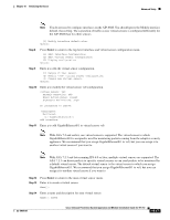
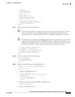
Advanced Setup Chapter 10 Initializing the Sensor Description[Created via setup by user cisco]: New Sensor Anomaly Detection Configuration [1] ad0 [2] Create a new anomaly detection configuration Option[2]: Step 15 Enter 1 to use the existing anomaly-detection configuration, ad0. Signature Definition Configuration [1] sig0 [2] Create a new signature definition configuration Option[2]: Step 16 Step 17 Enter 2 to create a signature-definition configuration file. Enter the signature-definition configuration name, newSig. Event Action Rules Configuration [1] rules0 [2] Create a new event action rules configuration Option[2]: Step 18 Enter 1 to use the existing event-action-rules configuration, rules0. Note If GigabitEthernet0/1 has not been assigned to vs0, you are prompted to assign it to the new virtual sensor. Note With ASA 7.2 and earlier, one virtual sensor is supported. The virtual sensor to which GigabitEthernet0/1 is assigned is used for monitoring packets coming from the adaptive security appliance. We recommend that you assign GigabitEthernet0/1 to vs0, but you can assign it to another virtual sensor if you want to. Note With ASA 7.2.3 and later with IPS 6.0, multiple virtual sensors are supported. The ASA 7.2.3 can direct packets to specific virtual sensors or can send packets to be monitored by a default virtual sensor. The default virtual sensor is the virtual sensor to which you assign GigabitEthernet0/1. We recommend that you assign GigabitEthernet0/1 to vs0, but you can assign it to another virtual sensor if you want to. Virtual Sensor: newVs Anomaly Detection: ad0 Event Action Rules: rules0 Signature Definitions: newSig Monitored: GigabitEthernet0/1 [1] Remove virtual sensor. [2] Modify "newVs" virtual sensor configuration. [3] Modify "vs0" virtual sensor configuration. [4] Create new virtual sensor. Option: Step 19 Press Enter to exit the interface and virtual sensor configuration menu. Modify default threat prevention settings?[no]: Step 20 Enter yes if you want to modify the default threat prevention settings. 10-18 Cisco Intrusion Prevention System Appliance and Module Installation Guide for IPS 7.0 OL-18504-01
-
 1
1 -
2
-
3
-
4
-
5
-
6
-
7
-
8
-
9
-
10
-
11
-
12
-
13
-
14
-
15
-
16
-
17
-
18
-
19
-
20
-
21
-
22
-
23
-
24
-
25
-
26
-
27
-
28
-
29
-
30
-
31
-
32
-
33
-
34
-
35
-
36
-
37
-
38
-
39
-
40
-
41
-
42
-
43
-
44
-
45
-
46
-
47
-
48
-
49
-
50
-
51
-
52
-
53
-
54
-
55
-
56
-
57
-
58
-
59
-
60
-
61
-
62
-
63
-
64
-
65
-
66
-
67
-
68
-
69
-
70
-
71
-
72
-
73
-
74
-
75
-
76
-
77
-
78
-
79
-
80
-
81
-
82
-
83
-
84
-
85
-
86
-
87
-
88
-
89
-
90
-
91
-
92
-
93
-
94
-
95
-
96
-
97
-
98
-
99
-
100
-
101
-
102
-
103
-
104
-
105
-
106
-
107
-
108
-
109
-
110
-
111
-
112
-
113
-
114
-
115
-
116
-
117
-
118
-
119
-
120
-
121
-
122
-
123
-
124
-
125
-
126
-
127
-
128
-
129
-
130
-
131
-
132
-
133
-
134
-
135
-
136
-
137
-
138
-
139
-
140
-
141
-
142
-
143
-
144
-
145
-
146
-
147
-
148
-
149
-
150
-
151
-
152
-
153
-
154
-
155
-
156
-
157
-
158
-
159
-
160
-
161
-
162
-
163
-
164
-
165
-
166
-
167
-
168
-
169
-
170
-
171
-
172
-
173
-
174
-
175
-
176
-
177
-
178
-
179
-
180
-
181
-
182
-
183
-
184
-
185
-
186
-
187
-
188
-
189
-
190
-
191
-
192
-
193
-
194
-
195
-
196
-
197
-
198
-
199
-
200
-
201
-
202
-
 203
203 -
 204
204 -
 205
205 -
 206
206 -
 207
207 -
 208
208 -
 209
209 -
 210
210 -
 211
211 -
 212
212 -
 213
213 -
214
-
215
-
216
-
217
-
218
-
219
-
220
-
221
-
222
-
223
-
224
-
225
-
226
-
227
-
228
-
229
-
230
-
231
-
232
-
233
-
234
-
235
-
236
-
237
-
238
-
239
-
240
-
241
-
242
-
243
-
244
-
245
-
246
-
247
-
248
-
249
-
250
-
251
-
252
-
253
-
254
-
255
-
256
-
257
-
258
-
259
-
260
-
261
-
262
-
263
-
264
-
265
-
266
-
267
-
268
-
269
-
270
-
271
-
272
-
273
-
274
-
275
-
276
-
277
-
278
-
279
-
280
-
281
-
282
-
283
-
284
-
285
-
286
-
287
-
288
-
289
-
290
-
291
-
292
-
293
-
294
-
295
-
296
-
297
-
298
-
299
-
300
-
301
-
302
-
303
-
304
-
305
-
306
-
307
-
308
-
309
-
310
-
311
-
312
-
313
-
314
-
315
-
316
-
317
-
318
-
319
-
320
-
321
-
322
-
323
-
324
-
325
-
326
-
327
-
328
-
329
-
330
-
331
-
332
-
333
-
334
-
335
-
336
-
337
-
338
-
339
-
340
-
341
-
342
-
343
-
344
-
345
-
346
-
347
-
348
-
349
-
350
-
351
-
352
-
353
-
354
-
355
-
356
-
357
-
358
-
359
-
360
-
361
-
362
-
363
-
364
-
365
-
366
-
367
-
368
-
369
-
370
-
371
-
372
-
373
-
374
-
375
-
376
-
377
-
378
-
379
-
380
-
381
-
382
-
383
-
384
-
385
-
386
-
387
-
388
-
389
-
390
-
391
-
392
-
393
-
394
-
395
-
396
-
397
-
398
-
399
-
400
-
401
-
402
-
403
-
404
-
405
-
406
-
407
-
408
-
409
-
410
-
411
-
412
 |
 |