Cisco IPS-4255-K9 Installation Guide - Page 250
Understanding ROMMON, Supported TFTP Servers, Connecting an Appliance to a Terminal Server - remote control
 |
UPC - 746320951096
View all Cisco IPS-4255-K9 manuals
Add to My Manuals
Save this manual to your list of manuals |
Page 250 highlights
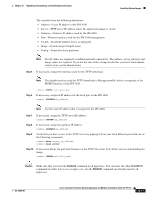
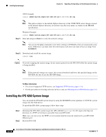
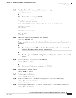
Installing System Images Chapter 12 Upgrading, Downgrading, and Installing System Images Understanding ROMMON Some Cisco sensors include a preboot CLI called ROMMON, which lets you boot images on sensors where the image on the primary device is missing, corrupt, or otherwise unable to boot the normal application. ROMMON is particularly useful for recovering remote sensors as long as the serial console port is available. Access to ROMMON is available only through the serial console port, a Cisco-standard asynchronous RS-232C DTE available in an RJ-45F connector on the sensor chassis. The serial port is configured for 9600 baud, 8 data bits, 1 stop bit, no parity, and no flow control. For More Information For the procedure for using a terminal server, see Connecting an Appliance to a Terminal Server, page 12-14. Supported TFTP Servers ROMMON uses TFTP to download an image and launch it. TFTP does not address network issues such as latency or error recovery. It does implement a limited packet integrity check so that packets arriving in sequence with the correct integrity value have an extremely low probability of error. But TFTP does not offer pipelining so the total transfer time is equal to the number of packets to be transferred times the network average RTT. Because of this limitation, we recommend that the TFTP server be located on the same LAN segment as the sensor. Any network with an RTT less than a 100 milliseconds should provide reliable delivery of the image. Some TFTP servers limit the maximum file size that can be transferred to ~32 MB. Therefore, we recommend the following TFTP servers: • For Windows: Tftpd32 version 2.0, available at: http://tftpd32.jounin.net/ • For UNIX: Tftp-hpa series, available at: http://www.kernel.org/pub/software/network/tftp/ Connecting an Appliance to a Terminal Server A terminal server is a router with multiple, low speed, asynchronous ports that are connected to other serial devices. You can use terminal servers to remotely manage network equipment, including appliances. To set up a Cisco terminal server with RJ-45 or hydra cable assembly connections, follow these steps: Step 1 Connect to a terminal server using one of the following methods: • For terminal servers with RJ-45 connections, connect a 180 rollover cable from the console port on the appliance to a port on the terminal server. • For hydra cable assemblies, connect a straight-through patch cable from the console port on the appliance to a port on the terminal server. 12-14 Cisco Intrusion Prevention System Appliance and Module Installation Guide for IPS 7.0 OL-18504-01
-
 1
1 -
2
-
3
-
4
-
5
-
6
-
7
-
8
-
9
-
10
-
11
-
12
-
13
-
14
-
15
-
16
-
17
-
18
-
19
-
20
-
21
-
22
-
23
-
24
-
25
-
26
-
27
-
28
-
29
-
30
-
31
-
32
-
33
-
34
-
35
-
36
-
37
-
38
-
39
-
40
-
41
-
42
-
43
-
44
-
45
-
46
-
47
-
48
-
49
-
50
-
51
-
52
-
53
-
54
-
55
-
56
-
57
-
58
-
59
-
60
-
61
-
62
-
63
-
64
-
65
-
66
-
67
-
68
-
69
-
70
-
71
-
72
-
73
-
74
-
75
-
76
-
77
-
78
-
79
-
80
-
81
-
82
-
83
-
84
-
85
-
86
-
87
-
88
-
89
-
90
-
91
-
92
-
93
-
94
-
95
-
96
-
97
-
98
-
99
-
100
-
101
-
102
-
103
-
104
-
105
-
106
-
107
-
108
-
109
-
110
-
111
-
112
-
113
-
114
-
115
-
116
-
117
-
118
-
119
-
120
-
121
-
122
-
123
-
124
-
125
-
126
-
127
-
128
-
129
-
130
-
131
-
132
-
133
-
134
-
135
-
136
-
137
-
138
-
139
-
140
-
141
-
142
-
143
-
144
-
145
-
146
-
147
-
148
-
149
-
150
-
151
-
152
-
153
-
154
-
155
-
156
-
157
-
158
-
159
-
160
-
161
-
162
-
163
-
164
-
165
-
166
-
167
-
168
-
169
-
170
-
171
-
172
-
173
-
174
-
175
-
176
-
177
-
178
-
179
-
180
-
181
-
182
-
183
-
184
-
185
-
186
-
187
-
188
-
189
-
190
-
191
-
192
-
193
-
194
-
195
-
196
-
197
-
198
-
199
-
200
-
201
-
202
-
203
-
204
-
205
-
206
-
207
-
208
-
209
-
210
-
211
-
212
-
213
-
214
-
215
-
216
-
217
-
218
-
219
-
220
-
221
-
222
-
223
-
224
-
225
-
226
-
227
-
228
-
229
-
230
-
231
-
232
-
233
-
234
-
235
-
236
-
237
-
238
-
239
-
240
-
241
-
242
-
243
-
244
-
 245
245 -
 246
246 -
 247
247 -
 248
248 -
 249
249 -
 250
250 -
 251
251 -
 252
252 -
 253
253 -
 254
254 -
 255
255 -
256
-
257
-
258
-
259
-
260
-
261
-
262
-
263
-
264
-
265
-
266
-
267
-
268
-
269
-
270
-
271
-
272
-
273
-
274
-
275
-
276
-
277
-
278
-
279
-
280
-
281
-
282
-
283
-
284
-
285
-
286
-
287
-
288
-
289
-
290
-
291
-
292
-
293
-
294
-
295
-
296
-
297
-
298
-
299
-
300
-
301
-
302
-
303
-
304
-
305
-
306
-
307
-
308
-
309
-
310
-
311
-
312
-
313
-
314
-
315
-
316
-
317
-
318
-
319
-
320
-
321
-
322
-
323
-
324
-
325
-
326
-
327
-
328
-
329
-
330
-
331
-
332
-
333
-
334
-
335
-
336
-
337
-
338
-
339
-
340
-
341
-
342
-
343
-
344
-
345
-
346
-
347
-
348
-
349
-
350
-
351
-
352
-
353
-
354
-
355
-
356
-
357
-
358
-
359
-
360
-
361
-
362
-
363
-
364
-
365
-
366
-
367
-
368
-
369
-
370
-
371
-
372
-
373
-
374
-
375
-
376
-
377
-
378
-
379
-
380
-
381
-
382
-
383
-
384
-
385
-
386
-
387
-
388
-
389
-
390
-
391
-
392
-
393
-
394
-
395
-
396
-
397
-
398
-
399
-
400
-
401
-
402
-
403
-
404
-
405
-
406
-
407
-
408
-
409
-
410
-
411
-
412
 |
 |