Netgear GS418TPP User Manual
Netgear GS418TPP Manual
 |
View all Netgear GS418TPP manuals
Add to My Manuals
Save this manual to your list of manuals |
Netgear GS418TPP manual content summary:
- Netgear GS418TPP | User Manual - Page 1
ProSAFE 8-Port or 16-Port Gigabit Smart Managed Switch with PoE+ and 2 SFP Ports Models GS418TPP, GS510TLP, and GS510TPP User Manual April 2017 202-11733-01 350 East Plumeria Drive San Jose, CA 95134 USA - Netgear GS418TPP | User Manual - Page 2
ProSAFE 8-Port or 16-Port Gigabit Smart Managed Switch Model GS418TPP, GS510TLP, and GS510TPP Support Thank you for purchasing this NETGEAR product. You can visit www.netgear.com/support to register your product, get help, access the latest downloads and user manuals, and join our community. We - Netgear GS418TPP | User Manual - Page 3
Overview 11 Change the Default IP Address of the Switch 11 Discover a Switch in a Network With a DHCP Server 12 Discover a Switch in a Network to the Support WebSite 28 User Guide 29 Register Your Product 29 Chapter 2 Configure System Information View and Configure the Switch Management - Netgear GS418TPP | User Manual - Page 4
ProSAFE 8-Port or 16-Port Gigabit Smart Managed Switch Model GS418TPP, GS510TLP, and GS510TPP Configure the PoE Port Settings 77 Configure SNMP 80 Configure the SNMPv1/v2 Community 80 Configure SNMPv1/v2 Trap Settings 83 Configure SNMPv1/v2 Trap Flags 85 View the Supported MIBs 86 Configure - Netgear GS418TPP | User Manual - Page 5
ProSAFE 8-Port or 16-Port Gigabit Smart Managed Switch Model GS418TPP, GS510TLP, and GS510TPP OUI-Based Port Settings 154 Manage the OUI Table 155 Display the Auto-VoIP Status 157 Configure Spanning Tree Protocol 158 Configure STP Settings 159 Configure CST Settings 161 Configure CST Port - Netgear GS418TPP | User Manual - Page 6
ProSAFE 8-Port or 16-Port Gigabit Smart Managed Switch Model GS418TPP, GS510TLP, and GS510TPP Configure Layer 2 Loop Protection on a Port 209 Chapter 4 Configure Routing Configure IP Settings 212 Configure the Router IP 212 IP Configure Quality of Service Manage Class of Service 250 CoS - Netgear GS418TPP | User Manual - Page 7
ProSAFE 8-Port or 16-Port Gigabit Smart Managed Switch Model GS418TPP, GS510TLP, and GS510TPP Configure the DiffServ Service Interface 276 View DiffServ Service Statistics 278 Chapter 6 Manage Device Security Management Security Settings 281 Change the Password 281 RADIUS Overview 282 Configure - Netgear GS418TPP | User Manual - Page 8
ProSAFE 8-Port or 16-Port Gigabit Smart Managed Switch Model GS418TPP, GS510TLP, and GS510TPP View Port Statistics 376 View Detailed Port Configure Port Mirroring 398 Chapter 8 Maintenance Reboot the Switch 402 Reset the Switch to Its Factory Default Settings 402 Export a File From the Switch - Netgear GS418TPP | User Manual - Page 9
ProSAFE 8-Port or 16-Port Gigabit Smart Managed Switch Model GS418TPP, GS510TLP, and GS510TPP Default Settings Switch Default Settings 447 General Feature Default Settings 448 System Setup and Maintenance Settings 455 Port Characteristics 455 Traffic Control Settings 456 Quality of Service - Netgear GS418TPP | User Manual - Page 10
describes how you can configure and operate the NETGEAR ProSAFE® 8-Port or 16-Port Gigabit Smart Managed Switch Model GS418TPP, GS510TLP, and GS510TPP by using the web-based management interface. The manual describes the software configuration procedures and explains the options that are available - Netgear GS418TPP | User Manual - Page 11
ProSAFE 8-Port or 16-Port Gigabit Smart Managed Switch Model GS418TPP, GS510TLP, and GS510TPP Switch Management Interface Overview The switch provides administrative management options that let you configure, monitor, and control the network. Using the web browser-based management interface, you can - Netgear GS418TPP | User Manual - Page 12
ProSAFE 8-Port or 16-Port Gigabit Smart Managed Switch Model GS418TPP, GS510TLP, and GS510TPP Discover a Switch in a Network With a DHCP Server This section describes how to set up your switch in a network that includes a DHCP server. The DHCP client on the switch is enabled by default. When you - Netgear GS418TPP | User Manual - Page 13
ProSAFE 8-Port or 16-Port Gigabit Smart Managed Switch Model GS418TPP, GS510TLP, and GS510TPP The Smart Control Center launches a browser that displays the login page of the selected device. Use your web browser to manage your switch. The default password is password. For more information about the - Netgear GS418TPP | User Manual - Page 14
ProSAFE 8-Port or 16-Port Gigabit Smart Managed Switch Model GS418TPP, GS510TLP, and GS510TPP 9. Type your password to continue with the configuration change. Tip: You must enter the current password each time that you use the Smart Control Center to update the switch settings. The default password - Netgear GS418TPP | User Manual - Page 15
ProSAFE 8-Port or 16-Port Gigabit Smart Managed Switch Model GS418TPP, GS510TLP, and GS510TPP To modify the IP address radio button and change the IP address of the computer to an address in the 192.168.0.0 network, such as 192.168.0.200. The IP address must be different from that of the switch - Netgear GS418TPP | User Manual - Page 16
ProSAFE 8-Port or 16-Port Gigabit Smart Managed Switch Model GS418TPP, GS510TLP, and GS510TPP WARNING: When you change the IP address of your administrative system, you lose your connection to the rest of the network. Be sure to write down your current network address settings - Netgear GS418TPP | User Manual - Page 17
ProSAFE 8-Port or 16-Port Gigabit Smart Managed Switch Model GS418TPP, GS510TLP, and GS510TPP Access the Web Browser-Based Management Interface You must be able to ping the IP address of the switch from your administrative system for web access to be available. If you used the Smart Control Center - Netgear GS418TPP | User Manual - Page 18
ProSAFE 8-Port or 16-Port Gigabit Smart Managed Switch Model GS418TPP, GS510TLP, and GS510TPP Supported Web Browsers The following browsers were tested and support the web browser-based management interface. Later browser versions might function fine but were not tested. The supported web browsers - Netgear GS418TPP | User Manual - Page 19
ProSAFE 8-Port or 16-Port Gigabit Smart Managed Switch Model GS418TPP, GS510TLP, and GS510TPP Navigation tab Configuration tabs along the top of the web interface give you quick access to the various switch functions. The tabs are always available and remain constant, regardless of which feature you - Netgear GS418TPP | User Manual - Page 20
ProSAFE 8-Port or 16-Port Gigabit Smart Managed Switch Model GS418TPP, GS510TLP, and GS510TPP Link Submenu links Cancel button cancels the configuration on the page and resets the data on the page to the previous values of the switch. Clicking the Delete button removes the selected item - Netgear GS418TPP | User Manual - Page 21
ProSAFE 8-Port or 16-Port Gigabit Smart Managed Switch Model GS418TPP, GS510TLP, and GS510TPP User-Defined Fields User-defined fields can contain 1 to 159 characters, unless otherwise noted on the configuration web page. All characters can - Netgear GS418TPP | User Manual - Page 22
ProSAFE 8-Port or 16-Port Gigabit Smart Managed Switch Model GS418TPP, GS510TLP, and GS510TPP Depending upon the status of the port, the port color in Device View is either red, green, or black. • Green indicates that the port is linking up. • Red indicates that an error occurred on the port or that - Netgear GS418TPP | User Manual - Page 23
ProSAFE 8-Port or 16-Port Gigabit Smart Managed Switch Model GS418TPP, GS510TLP, and GS510TPP Power LED The Power LED is a bicolor LED that serves as an indicator of power and diagnostic status: • Solid green. The power is supplied to the switch and operating normally. • Solid yellow. The system is - Netgear GS418TPP | User Manual - Page 24
ProSAFE 8-Port or 16-Port Gigabit Smart Managed Switch Model GS418TPP, GS510TLP, and GS510TPP Configure Interface Settings For some features that allow you to configure interface settings, you can apply the same settings simultaneously to any of the following: • A single port • Multiple ports • All - Netgear GS418TPP | User Manual - Page 25
ProSAFE 8-Port or 16-Port Gigabit Smart Managed Switch Model GS418TPP, GS510TLP, and GS510TPP 4. Configure the desired settings. 5. Click the Apply button. The updated configuration is sent to the switch. Configuration changes take effect immediately. To configure a single LAG by using the Go To - Netgear GS418TPP | User Manual - Page 26
ProSAFE 8-Port or 16-Port Gigabit Smart Managed Switch Model GS418TPP, GS510TLP, and GS510TPP To configure a single LAG: 1. Click the LAGS link or the All link to display the LAGs. 2. Select the check box next to - Netgear GS418TPP | User Manual - Page 27
ProSAFE 8-Port or 16-Port Gigabit Smart Managed Switch Model GS418TPP, GS510TLP, and GS510TPP To configure all ports: 1. Ensure that the page is displaying only ports, and not LAGs. 2. Select the check box in the heading row. The check boxes for all ports are selected and the rows for all ports - Netgear GS418TPP | User Manual - Page 28
Change the Default IP Address of the Switch on page 11. The login window opens. 4. Enter the switch's password in the Password field. The default password is password. The System Information page displays. 5. Select Help > Support. The Support page displays. 6. To access the NETGEAR support site for - Netgear GS418TPP | User Manual - Page 29
ProSAFE 8-Port or 16-Port Gigabit Smart Managed Switch Model GS418TPP, GS510TLP, and GS510TPP User Guide The user manual (the guide you are now reading) is available at the NETGEAR download center at downloadcenter.netgear.com. To access the user manual online from the web browser-based management - Netgear GS418TPP | User Manual - Page 30
2. Configure System Information 2 This chapter covers the following topics: • View and Configure the Switch Management Settings • Use the Device View • Configure PoE • Configure SNMP • Configure LLDP • Configure DHCP L2 Relay, DHCP Snooping, and Dynamic ARP Inspection • Set Up PoE - Netgear GS418TPP | User Manual - Page 31
ProSAFE 8-Port or 16-Port Gigabit Smart Managed Switch Model GS418TPP, GS510TLP, and GS510TPP View and Configure the Switch Management Settings This section describes how to display the switch status and specify some basic switch information, such as the management interface IP address, system clock - Netgear GS418TPP | User Manual - Page 32
ProSAFE 8-Port or 16-Port Gigabit Smart Managed Switch Model GS418TPP, GS510TLP, and GS510TPP 5. Define the following fields: • System Name. Enter the name to identify this switch. You can use up to 255 alphanumeric characters. The default is blank. • System Location. Enter the location of this - Netgear GS418TPP | User Manual - Page 33
ProSAFE 8-Port or 16-Port Gigabit Smart Managed Switch Model GS418TPP, GS510TLP, and GS510TPP View the Temperature Sensor Information Note: The temperature sensor information is available for model GS418TPP only. You can view the current temperature of the temperature sensors. The temperature is - Netgear GS418TPP | User Manual - Page 34
ProSAFE 8-Port or 16-Port Gigabit Smart Managed Switch Model GS418TPP, GS510TLP, and GS510TPP View the Fan Status Note: The fan status information is available for models GS418TPP and GS510TPP only. You can view the status of the fans in all units. These fans remove the heat generated by the power, - Netgear GS418TPP | User Manual - Page 35
ProSAFE 8-Port or 16-Port Gigabit Smart Managed Switch Model GS418TPP, GS510TLP, and GS510TPP View the Power Supplies You can view s the status of the power supplies. To view the power supplies status: 1. Connect your computer to the same network as the switch. You can use a WiFi or wired - Netgear GS418TPP | User Manual - Page 36
ProSAFE 8-Port or 16-Port Gigabit Smart Managed Switch Model GS418TPP, GS510TLP, and GS510TPP 3. In the address field of your web browser, enter the IP address of the switch. If you do not know the IP address of the switch, see Change the Default IP Address of the Switch on page 11. The login window - Netgear GS418TPP | User Manual - Page 37
ProSAFE 8-Port or 16-Port Gigabit Smart Managed Switch Model GS418TPP, GS510TLP, and GS510TPP The default password is password. The System switch that is off-network using an Ethernet cable. 2. Launch a web browser. 3. In the address field of your web browser, enter the IP address of the switch - Netgear GS418TPP | User Manual - Page 38
ProSAFE 8-Port or 16-Port Gigabit Smart Managed Switch Model GS418TPP, GS510TLP, and GS510TPP If you do not know the IP address of the switch, see Change the Default IP Address of the Switch on page 11. The login window opens. 4. Enter the switch's password in the Password field. The default - Netgear GS418TPP | User Manual - Page 39
ProSAFE 8-Port or 16-Port Gigabit Smart Managed Switch Model GS418TPP, GS510TLP, and GS510TPP View USB Device Information Note: Model GS418TPP supports a USB port but models GS510TLP and GS510TPP do not. Therefore, the information in this section refers to model GS418TPP only. You can display the - Netgear GS418TPP | User Manual - Page 40
ProSAFE 8-Port or 16-Port Gigabit Smart Managed Switch Model GS418TPP, GS510TLP, and GS510TPP The Device Status field displays the current status of the device. The status is one of the following: • Active. The device is USB plugged in and recognized by the switch. • Inactive. The device is not - Netgear GS418TPP | User Manual - Page 41
ProSAFE 8-Port or 16-Port Gigabit Smart Managed Switch Model GS418TPP, GS510TLP, and GS510TPP 4. Enter the switch's password in the Password field. The default password is password. The System Information page displays. 5. Select System > Management > IP Configuration. The IP Configuration page - Netgear GS418TPP | User Manual - Page 42
ProSAFE 8-Port or 16-Port Gigabit Smart Managed Switch Model GS418TPP, GS510TLP, and GS510TPP The following requirements apply to the management VLAN: • Only one management VLAN can be active at a time. • When a new management VLAN is - Netgear GS418TPP | User Manual - Page 43
ProSAFE 8-Port or 16-Port Gigabit Smart Managed Switch Model GS418TPP, GS510TLP, and GS510TPP 6. Ensure that the Admin Mode Enable radio button is selected. 7. Determine how the switch acquires an IPv6 address: • IPv6 Address Auto Configuration Mode. When this mode is enabled, the network interface - Netgear GS418TPP | User Manual - Page 44
ProSAFE 8-Port or 16-Port Gigabit Smart Managed Switch Model GS418TPP, GS510TLP, and GS510TPP The login window opens. 4. Enter the switch's password in the Password field. The default password is password Time Settings The switch supports the Simple Network manually. Configure System Information 44 - Netgear GS418TPP | User Manual - Page 45
ProSAFE 8-Port or 16-Port Gigabit Smart Managed Switch Model GS418TPP, GS510TLP, and GS510TPP Configure the Time Setting Manually You can view and adjust date and time settings. To manually configure the time setting: 1. Connect your computer to the same network as the switch. You can use a WiFi - Netgear GS418TPP | User Manual - Page 46
ProSAFE 8-Port or 16-Port Gigabit Smart Managed Switch Model GS418TPP, GS510TLP, and GS510TPP Configure the Time Settings With SNTP To configure the time by using SNTP: 1. Connect your computer to the same network as the switch. You can use a WiFi or wired connection to connect your computer to - Netgear GS418TPP | User Manual - Page 47
ProSAFE 8-Port or 16-Port Gigabit Smart Managed Switch Model GS418TPP, GS510TLP, and GS510TPP 9. In the Port field, specify the local UDP port that the SNTP client receives server packets on. The allowed range is 1025 to 65535 and 123. The default value is 123. When the default value is configured, - Netgear GS418TPP | User Manual - Page 48
ProSAFE 8-Port or 16-Port Gigabit Smart Managed Switch Model GS418TPP, GS510TLP, and GS510TPP Configure the Global SNTP Settings To configure the global SNTP settings: 1. Connect your computer to the same network as the switch. You can use a WiFi or wired connection to connect your computer to the - Netgear GS418TPP | User Manual - Page 49
ProSAFE 8-Port or 16-Port Gigabit Smart Managed Switch Model GS418TPP, GS510TLP, and GS510TPP determine the time and, for an SNTP response to a unicast poll request. The allowed range is 1 to 30. The default value is 5. 11. In the Unicast Poll Retry field, specify the number of times to retry - Netgear GS418TPP | User Manual - Page 50
ProSAFE 8-Port or 16-Port Gigabit Smart Managed Switch Model GS418TPP, GS510TLP, and GS510TPP 15. Click the Apply button. The updated configuration is sent to the switch. Configuration changes take effect immediately. 16. To refresh the page, click the Update button. View SNTP Global Status When you - Netgear GS418TPP | User Manual - Page 51
ProSAFE 8-Port or 16-Port Gigabit Smart Managed Switch Model GS418TPP, GS510TLP, and GS510TPP 6. Click the Update button to update the page with the latest information about the switch the client supports. Supported mode The SNTP modes that the client supports. Multiple modes can be supported by a - Netgear GS418TPP | User Manual - Page 52
ProSAFE 8-Port or 16-Port Gigabit Smart Managed Switch Model GS418TPP, GS510TLP, and GS510TPP Configure an SNTP Server SNTP assures accurate network device clock time synchronization up to the millisecond. Time synchronization is performed by a network SNTP server. The switch which the IP address is - Netgear GS418TPP | User Manual - Page 53
ProSAFE 8-Port or 16-Port Gigabit Smart Managed Switch Model GS418TPP, GS510TLP, and GS510TPP 2. Launch a web browser. 3. In the address field of your web browser, enter the IP address of the switch. If you do not know the IP address of the switch, see Change the Default IP Address of the Switch on - Netgear GS418TPP | User Manual - Page 54
ProSAFE 8-Port or 16-Port Gigabit Smart Managed Switch Model GS418TPP, GS510TLP, and GS510TPP The range is 1 to 4. The default value is 4. 11. Click the Add button. The SNTP server entry is added. This sends the updated configuration to the switch. Configuration changes take effect immediately. 12. - Netgear GS418TPP | User Manual - Page 55
ProSAFE 8-Port or 16-Port Gigabit Smart Managed Switch Model GS418TPP, GS510TLP, and GS510TPP 2. Launch a web browser. 3. In the address field of your web browser, enter the IP address of the switch. If you do not know the IP address of the switch, see Change the Default IP Address of the Switch on - Netgear GS418TPP | User Manual - Page 56
ProSAFE 8-Port or 16-Port Gigabit Smart Managed Switch Model GS418TPP, GS510TLP, and GS510TPP Configure Daylight Saving Time Settings You can configure settings for summer time, which is also known as daylight saving time. Used in - Netgear GS418TPP | User Manual - Page 57
ProSAFE 8-Port or 16-Port Gigabit Smart Managed Switch Model GS418TPP, GS510TLP, and GS510TPP • Recurring USA. annual basis. 7. Click the Apply button. The updated configuration is sent to the switch. Configuration changes take effect immediately. The fields in the following tables are visible only - Netgear GS418TPP | User Manual - Page 58
ProSAFE 8-Port or 16-Port Gigabit Smart Managed Switch Model GS418TPP, GS510TLP, and GS510TPP Table 16. Daylight saving setting is Non Recurring (continued) Field Ends At Offset Zone Description These fields are used to configure the end values of date and - Netgear GS418TPP | User Manual - Page 59
ProSAFE 8-Port or 16-Port Gigabit Smart Managed Switch Model GS418TPP, GS510TLP, and GS510TPP 6. To refresh the page, click the Update button. The following table displays the nonconfigurable daylight saving status information. Table 17. Daylight Saving ( - Netgear GS418TPP | User Manual - Page 60
ProSAFE 8-Port or 16-Port Gigabit Smart Managed Switch Model GS418TPP, GS510TLP, and GS510TPP Configure Denial of Service Settings You can configure the Denial of Service (DoS) settings for the switch. The switch provides support for classifying and blocking specific types of DoS attacks. Configure - Netgear GS418TPP | User Manual - Page 61
the IP address of the switch, see Change the Default IP Address of the Switch on page 11. The login window opens. 4. Enter the switch's password in the Password field. The default password is password. The System Information page displays. 5. Select System > Management > Denial of Service > Denial - Netgear GS418TPP | User Manual - Page 62
ProSAFE 8-Port or 16-Port Gigabit Smart Managed Switch Model GS418TPP, GS510TLP, and GS510TPP • Denial of Service Max ICMPv6 Packet Size. Specify the maximum IPv6 ICMP packet size allowed. If ICMPv6 DoS prevention is enabled, the switch drops IPv6 ICMP ping packets with a size greater than the - Netgear GS418TPP | User Manual - Page 63
ProSAFE 8-Port or 16-Port Gigabit Smart Managed Switch Model GS418TPP, GS510TLP, and GS510TPP Configure DNS Settings You can configure information about DNS servers that the network uses and how the switch operates as a DNS client. Configure Global DNS Settings You can configure global DNS settings - Netgear GS418TPP | User Manual - Page 64
ProSAFE 8-Port or 16-Port Gigabit Smart Managed Switch Model GS418TPP, GS510TLP, and GS510TPP When the system is performing a lookup on an unqualified host name, this field is provides the domain name (for example, if default domain name is netgear.com and the user enters test, then test is changed - Netgear GS418TPP | User Manual - Page 65
ProSAFE 8-Port or 16-Port Gigabit Smart Managed Switch Model GS418TPP, GS510TLP, and GS510TPP 4. Enter the switch's password in the Password field. The default password is password. The System Information page displays. 5. Select System > Management > DNS > Host Configuration. 6. In the Host Name (1 - Netgear GS418TPP | User Manual - Page 66
ProSAFE 8-Port or 16-Port Gigabit Smart Managed Switch Model GS418TPP, GS510TLP, and GS510TPP Change the Host Name or IP Address in an Entry of the Dynamic Host Mapping Table and View All Entries To change the host name or IP address in an entry of the dynamic host mapping table and view all - Netgear GS418TPP | User Manual - Page 67
ProSAFE 8-Port or 16-Port Gigabit Smart Managed Switch Model GS418TPP, GS510TLP, and GS510TPP Configure Green Ethernet Settings You can configure the green Ethernet features to reduce power consumption. To configure the Green Ethernet settings: 1. Connect - Netgear GS418TPP | User Manual - Page 68
ProSAFE 8-Port or 16-Port Gigabit Smart Managed Switch Model GS418TPP, GS510TLP, and GS510TPP Configure Green Ethernet Interface Settings You can configure per-port Green Ethernet settings. To configure the Green Ethernet interface settings: 1. Connect your computer to the same network as the - Netgear GS418TPP | User Manual - Page 69
ProSAFE 8-Port or 16-Port Gigabit Smart Managed Switch Model GS418TPP, GS510TLP, and GS510TPP The updated configuration is sent to the switch. Configuration changes take effect immediately. Configure Green Ethernet Local and Remote Devices You can view detailed per-port green Ethernet information - Netgear GS418TPP | User Manual - Page 70
ProSAFE 8-Port or 16-Port Gigabit Smart Managed Switch Model GS418TPP, GS510TLP, and GS510TPP 7. From the EEE Admin mode menu, select Enable or Disable. With the EEE mode enabled, the port transitions to low power mode during a link idle condition. The default system can support. Tw_sys_tx Echo - Netgear GS418TPP | User Manual - Page 71
ProSAFE 8-Port or 16-Port Gigabit Smart Managed Switch Model GS418TPP, GS510TLP, and GS510TPP Table 20. Green Ethernet Local Device Information (continued) Field Description Tw_sys_rx Echo (uSec) Integer that indicates the remote system's Receive Tw_sys that - Netgear GS418TPP | User Manual - Page 72
ProSAFE 8-Port or 16-Port Gigabit Smart Managed Switch Model GS418TPP, GS510TLP, and GS510TPP 7. Select the interface. The following table describes the nonconfigurable fields. Table 21. Green Ethernet Remote Device Information Field Description Remote ID The - Netgear GS418TPP | User Manual - Page 73
ProSAFE 8-Port or 16-Port Gigabit Smart Managed Switch Model GS418TPP, GS510TLP, and GS510TPP 6. To refresh the page saved on the switch in watts multiplied by hours if all green modes are enabled. Unit The unit ID. Green Features supported on this unit List of green features supported on the - Netgear GS418TPP | User Manual - Page 74
ProSAFE 8-Port or 16-Port Gigabit Smart Managed Switch Model GS418TPP, GS510TLP, and GS510TPP Table 22. Green Ethernet Statistics Summary information (continued) Field Description Energy Detect Operational Status Current operational status of the Energy Detect mode. - Netgear GS418TPP | User Manual - Page 75
ProSAFE 8-Port or 16-Port Gigabit Smart Managed Switch Model GS418TPP, GS510TLP, and GS510TPP 8. In the Max Samples to keep field, enter the maximum number of samples to keep. This is a global setting and is applied to all interfaces. The range is 1 to 168.The default statistics were reset. Use the - Netgear GS418TPP | User Manual - Page 76
ProSAFE 8-Port or 16-Port Gigabit Smart Managed Switch Model GS418TPP, GS510TLP, and GS510TPP If you do not know the IP address of the switch, see Change the Default IP Address of the Switch on page 11. The login window opens. 4. Enter the switch's password in the Password field. The default - Netgear GS418TPP | User Manual - Page 77
the IP address of the switch, see Change the Default IP Address of the Switch on page 11. The login window opens. 4. Enter the switch's password in the Password field. The default password is password. The System Information page displays. 5. Select System > PoE > Advanced > PoE Port Configuration - Netgear GS418TPP | User Manual - Page 78
ProSAFE 8-Port or 16-Port Gigabit Smart Managed Switch Model GS418TPP, GS510TLP, and GS510TPP 8. From the Port Priority menu, select the priority for the port in relation to other ports if the total power that the switch is capable of delivering exceeds the total power budget: • Low. Low priority. - Netgear GS418TPP | User Manual - Page 79
ProSAFE 8-Port or 16-Port Gigabit Smart Managed Switch Model GS418TPP, GS510TLP, and GS510TPP • 4pt 802.3af + Legacy. The port performs a 4-point resistive detection, and if required, continues with legacy detection. • Legacy. The port performs legacy detection. 13. From the Timer Schedule menu, - Netgear GS418TPP | User Manual - Page 80
ProSAFE 8-Port or 16-Port Gigabit Smart Managed Switch Model GS418TPP, GS510TLP, and GS510TPP Table 25. PoE Port Configuration (continued) Field Fault Status Description The error description when the PoE port is in a fault state. The possible values are as follows: • No Error. The port is not in - Netgear GS418TPP | User Manual - Page 81
ProSAFE 8-Port or 16-Port Gigabit Smart Managed Switch Model GS418TPP, GS510TLP, and GS510TPP 4. Enter the switch's password in the Password field. The default password is password , use a management station IP mask value of 255.255.255.255, and use that machine's IP address for client address. - Netgear GS418TPP | User Manual - Page 82
ProSAFE 8-Port or 16-Port Gigabit Smart Managed Switch Model GS418TPP, GS510TLP, and GS510TPP If you do not know the IP address of the switch, see Change the Default IP Address of the Switch on page 11. The login window opens. 4. Enter the switch's password in the Password field. The default - Netgear GS418TPP | User Manual - Page 83
ProSAFE 8-Port or 16-Port Gigabit Smart Managed Switch Model GS418TPP, GS510TLP, and GS510TPP Configure SNMPv1/v2 Trap Settings You can configure settings for each SNMPv1 or SNMPv2 management host that must receive notifications about traps - Netgear GS418TPP | User Manual - Page 84
ProSAFE 8-Port or 16-Port Gigabit Smart Managed Switch Model GS418TPP, GS510TLP, and GS510TPP Modify Information About an Existing SNMP Recipient To modify information about an existing SNMP recipient: 1. Connect your computer to the same network as the switch. You can use a WiFi or wired - Netgear GS418TPP | User Manual - Page 85
ProSAFE 8-Port or 16-Port Gigabit Smart Managed Switch Model GS418TPP, GS510TLP, and GS510TPP 5. Select System > SNMP > SNMP V1/V2 > Trap Configuration. The Trap Configuration page displays. 6. Select the check box next to the recipient to - Netgear GS418TPP | User Manual - Page 86
ProSAFE 8-Port or 16-Port Gigabit Smart Managed Switch Model GS418TPP, GS510TLP, and GS510TPP • Link Up/Down. When enabled, SNMP traps are sent when the administrative or operational state of a physical or logical link changes. The default is Enable. • Spanning Tree. When enabled, SNMP traps are - Netgear GS418TPP | User Manual - Page 87
ProSAFE 8-Port or 16-Port Gigabit Smart Managed Switch Model GS418TPP, GS510TLP, and GS510TPP The following table describes the SNMP Supported MIBs Status fields. Table 26. SNMP supported MIBs Field Name Description Description The RFC number if applicable and the name of the MIB. The RFC title - Netgear GS418TPP | User Manual - Page 88
ProSAFE 8-Port or 16-Port Gigabit Smart Managed Switch Model GS418TPP, GS510TLP, and GS510TPP b. In the Encryption Key field, enter an encryption code of eight or more alphanumeric characters. 8. Click the Apply button. The updated configuration is sent to the switch. Configuration changes take - Netgear GS418TPP | User Manual - Page 89
ProSAFE 8-Port or 16-Port Gigabit Smart Managed Switch Model GS418TPP, GS510TLP, and GS510TPP Configure LLDP Global Settings You can specify the global LLDP and LLDP-MED parameters that are applied to the switch. To configure global LLDP settings: 1. Connect your computer to the same network as - Netgear GS418TPP | User Manual - Page 90
know the IP address of the switch, see Change the Default IP Address of the Switch on page 11. The login window opens. 4. Enter the switch's password in the Password field. The default password is password. The System Information page displays. 5. Select System > LLDP > Advanced > LLDP Port Settings - Netgear GS418TPP | User Manual - Page 91
ProSAFE 8-Port or 16-Port Gigabit Smart Managed Switch Model GS418TPP, GS510TLP, and GS510TPP • To configure all interfaces with the same settings, select the check box in the heading row. 7. Use the following menus to configure the LLDP settings for the selected ports: • Admin Status. Select the - Netgear GS418TPP | User Manual - Page 92
ProSAFE 8-Port or 16-Port Gigabit Smart Managed Switch Model GS418TPP, GS510TLP, and GS510TPP If you do not know the IP address of the switch, see Change the Default IP Address of the Switch on page 11. The login window opens. 4. Enter the switch's password in the Password field. The default - Netgear GS418TPP | User Manual - Page 93
the IP address of the switch, see Change the Default IP Address of the Switch on page 11. The login window opens. 4. Enter the switch's password in the Password field. The default password is password. The System Information page displays. 5. Select System > LLDP > Advanced > LLDP-MED Port Settings - Netgear GS418TPP | User Manual - Page 94
ProSAFE 8-Port or 16-Port Gigabit Smart Managed Switch Model GS418TPP, GS510TLP, and GS510TPP Local Information You can view the data that each port advertises through LLDP. To view local LLDP information: 1. Connect your computer to the same network as the switch. You can use a WiFi or wired - Netgear GS418TPP | User Manual - Page 95
ProSAFE 8-Port or 16-Port Gigabit Smart Managed Switch Model GS418TPP, GS510TLP, and GS510TPP Field Description Interface The interface associated with the rest of the data in the row. Port ID Subtype The type of information used to identify the interface in the Port ID field. Port ID The - Netgear GS418TPP | User Manual - Page 96
ProSAFE 8-Port or 16-Port Gigabit Smart Managed Switch Model GS418TPP, GS510TLP, and GS510TPP Field VLAN ID VLAN Type User Priority DSCP Description The VLAN ID associated with the policy. Specifies whether the VLAN associated with - Netgear GS418TPP | User Manual - Page 97
ProSAFE 8-Port or 16-Port Gigabit Smart Managed Switch Model GS418TPP, GS510TLP, and GS510TPP The following table describes the information that displays for all LLDP neighbors that were discovered. Field MSAP Entry Local Port Chassis ID Subtype Chassis ID Port ID Subtype Port ID System Name - Netgear GS418TPP | User Manual - Page 98
ProSAFE 8-Port or 16-Port Gigabit Smart Managed Switch Model GS418TPP, GS510TLP, and GS510TPP Field Description Managed Addresses Address SubType The type of the management address. Address The advertised management address of the remote system. Interface SubType The port subtype. - Netgear GS418TPP | User Manual - Page 99
ProSAFE 8-Port or 16-Port Gigabit Smart Managed Switch Model GS418TPP , longitude, and altitude. The Emergency Call Service (ECS) Emergency Location Identification Number (ELIN Relay, DHCP Snooping, and Dynamic ARP Inspection The switch supports DHCP L2 Relay, DHCP snooping, and Dynamic ARP - Netgear GS418TPP | User Manual - Page 100
you do not know the IP address of the switch, see Change the Default IP Address of the Switch on page 11. The login window opens. 4. Enter the switch's password in the Password field. The default password is password. The System Information page displays. 5. Select System> Services > DHCP L2 Relay - Netgear GS418TPP | User Manual - Page 101
ProSAFE 8-Port or 16-Port Gigabit Smart Managed Switch Model GS418TPP, GS510TLP, and GS510TPP 6. Select the Enable radio button The default admin mode is disabled. 7. Click the Apply button. The updated configuration is sent to the switch. Configuration changes take effect immediately. DHCP L2 Relay - Netgear GS418TPP | User Manual - Page 102
ProSAFE 8-Port or 16-Port Gigabit Smart Managed Switch Model GS418TPP, GS510TLP, and GS510TPP 7. From the Admin Mode menu, select to enable or disable the DHCP L2 relay on the selected interface. The default is Disable. 8. From the 82 Option Trust Mode menu, select to enable or disable an interface - Netgear GS418TPP | User Manual - Page 103
ProSAFE 8-Port or 16-Port Gigabit Smart Managed Switch Model GS418TPP, GS510TLP, and GS510TPP The following table describes the nonconfigurable data that is displayed. Field Description Interface The interface from which the DHCP message is received. - Netgear GS418TPP | User Manual - Page 104
ProSAFE 8-Port or 16-Port Gigabit Smart Managed Switch Model GS418TPP, GS510TLP, and GS510TPP The login window opens. 4. Enter the switch's password in the Password field. The default password is password. The System Information page displays. 5. Select System> Services > DHCP Snooping > Global - Netgear GS418TPP | User Manual - Page 105
ProSAFE 8-Port or 16-Port Gigabit Smart Managed Switch Model GS418TPP, GS510TLP, and GS510TPP The System Information page displays. 5. Select System> Services > DHCP Snooping > Global Configuration. The DHCP Snooping Global Configuration page displays. 6. In the VLAN ID field, specify the VLAN on - Netgear GS418TPP | User Manual - Page 106
ProSAFE 8-Port or 16-Port Gigabit Smart Managed Switch Model GS418TPP, GS510TLP, and GS510TPP • To configure multiple the incoming rate of DHCP packets per second exceeds the configured burst interval per second, the port shuts down. If the rate limit value is N/A, then the burst interval is also - Netgear GS418TPP | User Manual - Page 107
ProSAFE 8-Port or 16-Port Gigabit Smart Managed Switch Model GS418TPP, GS510TLP, and GS510TPP 2. Launch a web browser. 3. In the address field of your web browser, enter the IP address of the switch. If you do not know the IP address of the switch, see Change the Default IP Address of the Switch on - Netgear GS418TPP | User Manual - Page 108
you do not know the IP address of the switch, see Change the Default IP Address of the Switch on page 11. The login window opens. 4. Enter the switch's password in the Password field. The default password is password. The System Information page displays. 5. Select System> Services > DHCP Snooping - Netgear GS418TPP | User Manual - Page 109
you do not know the IP address of the switch, see Change the Default IP Address of the Switch on page 11. The login window opens. 4. Enter the switch's password in the Password field. The default password is password. The System Information page displays. 5. Select System> Services > DHCP Snooping - Netgear GS418TPP | User Manual - Page 110
ProSAFE 8-Port or 16-Port Gigabit Smart Managed Switch Model GS418TPP, GS510TLP, and GS510TPP The following table describes the DAI drops ARP packets with an invalid IP address. The following IP addresses are considered invalid: • 0.0.0.0 • 255.255.255.255 • All IP multicast addresses • All class E - Netgear GS418TPP | User Manual - Page 111
ProSAFE 8-Port or 16-Port Gigabit Smart Managed Switch Model GS418TPP, GS510TLP, and GS510TPP The valid IP check is applied only on the sender IP address in ARP packets. In ARP response packets, the check is applied only on the target IP address. To configure the optional DAI features: 1. Connect - Netgear GS418TPP | User Manual - Page 112
If you do not know the IP address of the switch, see Change the Default IP Address of the Switch on page 11. The login window opens. 4. Enter the switch's password in the Password field. The default password is password. The System Information page displays. 5. Select System> Services > Dynamic ARP - Netgear GS418TPP | User Manual - Page 113
If you do not know the IP address of the switch, see Change the Default IP Address of the Switch on page 11. The login window opens. 4. Enter the switch's password in the Password field. The default password is password. The System Information page displays. 5. Select System> Services > Dynamic ARP - Netgear GS418TPP | User Manual - Page 114
ProSAFE 8-Port or 16-Port Gigabit Smart Managed Switch Model GS418TPP, GS510TLP, and GS510TPP 7. Next to l1, select the . The value can be set to -1, which means N/A. The rate limit range is 0-300. The default is 15 packets per second (pps). 10. In the Burst Interval(secs) field, specify the burst - Netgear GS418TPP | User Manual - Page 115
ProSAFE 8-Port or 16-Port Gigabit Smart Managed Switch Model GS418TPP, GS510TLP, and GS510TPP Configure a DAI ACL DAI relies on the information in the DHCP snooping bindings database to validate ARP packets. For networks that use static IP addresses and do not use DHCP, DAI access control lists ( - Netgear GS418TPP | User Manual - Page 116
ProSAFE 8-Port or 16-Port Gigabit Smart Managed Switch Model GS418TPP, GS510TLP, and GS510TPP 8. Click the ACL name. The ACL name is a hyperlink to the Dynamic ARP Inspection ACL Rule Configuration page. 9. From the ACL Name menu, select the DAI ACL to configure. 10. In the Source IP Address field, - Netgear GS418TPP | User Manual - Page 117
If you do not know the IP address of the switch, see Change the Default IP Address of the Switch on page 11. The login window opens. 4. Enter the switch's password in the Password field. The default password is password. The System Information page displays. 5. Select System> Services > Dynamic ARP - Netgear GS418TPP | User Manual - Page 118
ProSAFE 8-Port or 16-Port Gigabit Smart Managed Switch Model GS418TPP, GS510TLP, and GS510TPP The following table describes the nonconfigurable DAI statistics information that is displayed. Field VLAN DHCP Drops DHCP Permits ACL Drops ACL Permits Bad Source MAC Bad Dest MAC Invalid IP Forwarded - Netgear GS418TPP | User Manual - Page 119
ProSAFE 8-Port or 16-Port Gigabit Smart Managed Switch Model GS418TPP, GS510TLP, and GS510TPP Create a PoE Timer Schedule The maximum number of timer schedules that you can add is 100. To create a PoE timer schedule: 1. Connect your computer to the same network as the switch. You can use a WiFi or - Netgear GS418TPP | User Manual - Page 120
ProSAFE 8-Port or 16-Port Gigabit Smart Managed Switch Model GS418TPP, GS510TLP, and GS510TPP The default password is password. The System Information page displays. 5. Select System> Timer Schedule > Advanced > Timer Schedule Configuration. The Timer Schedule Configuration page displays. 6. In the - Netgear GS418TPP | User Manual - Page 121
ProSAFE 8-Port or 16-Port Gigabit Smart Managed Switch Model GS418TPP, GS510TLP, and GS510TPP To specify the settings for a PoE timer schedule that uses a recurring pattern: 1. Connect your computer to the same network as the switch. You can use a WiFi or wired connection to connect your computer - Netgear GS418TPP | User Manual - Page 122
ProSAFE 8-Port or 16-Port Gigabit Smart Managed Switch Model GS418TPP, GS510TLP, and GS510TPP e. From the Recurrence Pattern menu, select the pattern: • Daily. The timer schedule works with daily recurrence. The fields adjust. Either select the - Netgear GS418TPP | User Manual - Page 123
ProSAFE 8-Port or 16-Port Gigabit Smart Managed Switch Model GS418TPP, GS510TLP, and GS510TPP The System Information page displays. 5. Select System > Timer Schedule > Advanced > Timer Schedule Configuration. The Timer Schedule Configuration page displays. 6. From the Timer - Netgear GS418TPP | User Manual - Page 124
ProSAFE 8-Port or 16-Port Gigabit Smart Managed Switch Model GS418TPP, GS510TLP, and GS510TPP Delete a PoE Timer Schedule You can delete a PoE timer schedule that you no longer need. All entries that are part of the - Netgear GS418TPP | User Manual - Page 125
3. Configure Switching This chapter covers the following topics: • Configure Port Settings • Configure Link Aggregation Groups • Configure VLANs • Configure Auto-VoIP • Configure Spanning Tree Protocol • Configure Multicast • Configure Multicast VLAN Registration • View and Configure the MAC - Netgear GS418TPP | User Manual - Page 126
do not know the IP address of the switch, see Change the Default IP Address of the Switch on page 11. The login window opens. 4. Enter the switch's password in the Password field. The default password is password. The System Information page displays. 5. Select Switching > Ports > Port Configuration - Netgear GS418TPP | User Manual - Page 127
ProSAFE 8-Port or 16-Port Gigabit Smart Managed Switch Model GS418TPP, GS510TLP, and GS510TPP Note: After you change the autonegotiation mode, the switch the interface supports or is configured to use, including Ethernet header, CRC, and payload. The range is 1500 to 9198. The default maximum frame - Netgear GS418TPP | User Manual - Page 128
ProSAFE 8-Port or 16-Port Gigabit Smart Managed Switch Model GS418TPP, GS510TLP, and GS510TPP frame to stop traffic on the port if the amount of memory used by the packets on the port exceeds a preconfigured threshold and responds to pause requests from partner devices. The paused port does not - Netgear GS418TPP | User Manual - Page 129
ProSAFE 8-Port or 16-Port Gigabit Smart Managed Switch Model GS418TPP, GS510TLP, and GS510TPP A LAG interface can be either static or dynamic, but not both. All members of a LAG must participate in the same protocols. A static port channel interface does not require a partner system to be able to - Netgear GS418TPP | User Manual - Page 130
ProSAFE 8-Port or 16-Port Gigabit Smart Managed Switch Model GS418TPP, GS510TLP, and GS510TPP When the LAG is disabled, no traffic flows and LACPDUs are dropped, but the links that form the LAG are not released. The default LAG. The LAG is configured manually. The default is Static. • LACP. Disables - Netgear GS418TPP | User Manual - Page 131
ProSAFE 8-Port or 16-Port Gigabit Smart Managed Switch Model GS418TPP, GS510TLP, and GS510TPP The following table describes the nonconfigurable information displayed on the page. Table 31. LAG Configuration information Field LAG ID Active Ports LAG State Description Identification of the LAG. - Netgear GS418TPP | User Manual - Page 132
ProSAFE 8-Port or 16-Port Gigabit Smart Managed Switch Model GS418TPP, GS510TLP, and GS510TPP You can enter any string of up to 15 alphanumeric characters. A valid name must be specified for you to create the LAG. 8. In the Ports table, click each port that you want to include as a member of the - Netgear GS418TPP | User Manual - Page 133
ProSAFE 8-Port or 16-Port Gigabit Smart Managed Switch Model GS418TPP, GS510TLP, and GS510TPP A higher value indicates a lower priority. You can change the value of the parameter globally by specifying a priority from 1 to 65535. The default value is 32768. 7. Click the Apply button. The updated - Netgear GS418TPP | User Manual - Page 134
ProSAFE 8-Port or 16-Port Gigabit Smart Managed Switch Model GS418TPP, GS510TLP, and GS510TPP support only one default VLAN ID. You can define VLAN groups stored in the VLAN membership table. The switch supports up to 256 VLANs. VLAN 1 is created by default and is the default VLAN of which all ports - Netgear GS418TPP | User Manual - Page 135
ProSAFE 8-Port or 16-Port Gigabit Smart Managed Switch Model GS418TPP, GS510TLP, and GS510TPP Add a Internal VLAN To add an internal VLAN: 1. Connect your computer to the same network as the switch. You can use a WiFi or wired connection to connect your computer to the network, or connect directly - Netgear GS418TPP | User Manual - Page 136
ProSAFE 8-Port or 16-Port Gigabit Smart Managed Switch Model GS418TPP, GS510TLP, and GS510TPP The updated configuration is sent to the switch. Configuration changes take effect immediately. Delete a VLAN To delete a VLAN from the switch: 1. Connect your computer to the same network as the switch. - Netgear GS418TPP | User Manual - Page 137
ProSAFE 8-Port or 16-Port Gigabit Smart Managed Switch Model GS418TPP, GS510TLP, and GS510TPP If you do not know the IP address of the switch, see Change the Default IP Address of the Switch on page 11. The login window opens. 4. Enter the switch's password in the Password field. The default - Netgear GS418TPP | User Manual - Page 138
ProSAFE 8-Port or 16-Port Gigabit Smart Managed Switch Model GS418TPP, GS510TLP, and GS510TPP The System Information page displays. 5. Select Switching > VLAN > Advanced > VLAN Membership. 6. In the VLAN ID menu, select the VLAN ID. 7. In the Group Operation menu, select one of the following options - Netgear GS418TPP | User Manual - Page 139
ProSAFE 8-Port or 16-Port Gigabit Smart Managed Switch Model GS418TPP, GS510TLP, and GS510TPP 10. Click the Apply button. The updated configuration is sent to the switch. Configuration changes take effect immediately. The following table describes the nonconfigurable information displayed on the - Netgear GS418TPP | User Manual - Page 140
ProSAFE 8-Port or 16-Port Gigabit Smart Managed Switch Model GS418TPP, GS510TLP, and GS510TPP The following table describes the nonconfigurable information displayed on the page. Table 33. VLAN status Field VLAN ID VLAN Name VLAN Type Routing Interface Member Ports Definition The VLAN identifier - Netgear GS418TPP | User Manual - Page 141
ProSAFE 8-Port or 16-Port Gigabit Smart Managed Switch Model GS418TPP, GS510TLP, and GS510TPP If you do not know the IP address of the switch, see Change the Default IP Address of the Switch on page 11. The login window opens. 4. Enter the switch's password in the Password field. The default - Netgear GS418TPP | User Manual - Page 142
ProSAFE 8-Port or 16-Port Gigabit Smart Managed Switch Model GS418TPP, GS510TLP, and GS510TPP 12. From the Ingress Filtering menu, select one of the following options: • Enable. The frame is discarded if this port is not a member of the VLAN with which this frame is associated. In a tagged frame, - Netgear GS418TPP | User Manual - Page 143
ProSAFE 8-Port or 16-Port Gigabit Smart Managed Switch Model GS418TPP, GS510TLP, and GS510TPP Add a MAC-Based VLAN To add a MAC-based VLAN: 1. Connect your computer to the same network as the switch. You can use a WiFi or wired connection to connect your computer to the network, or connect - Netgear GS418TPP | User Manual - Page 144
ProSAFE 8-Port or 16-Port Gigabit Smart Managed Switch Model GS418TPP, GS510TLP, and GS510TPP 4. Enter the switch's password in the Password field. The default password is password. The System Information page displays. 5. Select Switching> VLAN > Advanced > MAC Based VLAN. The MAC Based VLAN - Netgear GS418TPP | User Manual - Page 145
ProSAFE 8-Port or 16-Port Gigabit Smart Managed Switch Model GS418TPP, GS510TLP, and GS510TPP The default password is password. The System Information page displays. 5. Select Switching> VLAN > Advanced > Protocol Based VLAN Group Configuration. 6. In the Group Name field, type a name for the new - Netgear GS418TPP | User Manual - Page 146
ProSAFE 8-Port or 16-Port Gigabit Smart Managed Switch Model GS418TPP, GS510TLP, and GS510TPP 3. In the address field of your web browser, enter the IP address of the switch. If you do not know the IP address of the switch, see Change the Default IP Address of the Switch on page 11. The login window - Netgear GS418TPP | User Manual - Page 147
ProSAFE 8-Port or 16-Port Gigabit Smart Managed Switch Model GS418TPP, GS510TLP, and GS510TPP Configure a Voice VLAN You can configure the parameters for a voice VLAN configuration. To configure a voice VLAN: 1. Connect your computer to the same network as the switch. You can use a WiFi or wired - Netgear GS418TPP | User Manual - Page 148
ProSAFE 8-Port or 16-Port Gigabit Smart Managed Switch Model GS418TPP, GS510TLP, and GS510TPP 8. From the Interface Mode menu, select the voice VLAN mode for selected interfaces: • Disable. This is the default value. • None. Allow the IP phone to use its own configuration to send untagged voice - Netgear GS418TPP | User Manual - Page 149
ProSAFE 8-Port or 16-Port Gigabit Smart Managed Switch Model GS418TPP, GS510TLP, and GS510TPP GARP is part of the IEEE 802.1p extension to its 802.1D (spanning tree) specification. It includes the following: • GARP Information - Netgear GS418TPP | User Manual - Page 150
of the switch, see Change the Default IP Address of the Switch on page 11. The login window opens. 4. Enter the switch's password in the Password field. The default password is password. The System Information page displays. 5. Select Switching> VLAN > Advanced > GARP Port Configuration. 6. Select - Netgear GS418TPP | User Manual - Page 151
ProSAFE 8-Port or 16-Port Gigabit Smart Managed Switch Model GS418TPP, GS510TLP, and GS510TPP 8. In the Join Timer field for the same attribute to maintain uninterrupted service. Enter a number between 20 and 600 (0.2 to 6.0 seconds). The default is 60 centiseconds (0.6 seconds). An instance - Netgear GS418TPP | User Manual - Page 152
of the switch, see Change the Default IP Address of the Switch on page 11. The login window opens. 4. Enter the switch's password in the Password field. The default password is password. The System Information page displays. 5. Select Switching > Auto-VoIP > Protocol-based > Port Settings. 6. From - Netgear GS418TPP | User Manual - Page 153
ProSAFE 8-Port or 16-Port Gigabit Smart Managed Switch Model GS418TPP, GS510TLP, and GS510TPP Configure Auto-VoIP OUI-Based Properties With Organizationally Unique Identifier (OUI)-based Auto-VoIP, voice prioritization is provided based on OUI bits. - Netgear GS418TPP | User Manual - Page 154
the IP address of the switch, see Change the Default IP Address of the Switch on page 11. The login window opens. 4. Enter the switch's password in the Password field. The default password is password. The System Information page displays. 5. Select Switching > Auto-VoIP > OUI-based > Port Settings - Netgear GS418TPP | User Manual - Page 155
ProSAFE 8-Port or 16-Port Gigabit Smart Managed Switch Model GS418TPP, GS510TLP, and GS510TPP Manage the OUI Table Device hardware manufacturers can include an OUI in a network adapter to help identify a hardware device. The OUI is a - Netgear GS418TPP | User Manual - Page 156
ProSAFE 8-Port or 16-Port Gigabit Smart Managed Switch Model GS418TPP, GS510TLP, and GS510TPP 6. In for the OUI. The maximum length of description is 32 characters. The following OUIs are present in the configuration by default: • 00:01:E3 - SIEMENS • 00:03:6B - CISCO1 • 00:12:43 - CISCO2 • 00:0F - Netgear GS418TPP | User Manual - Page 157
ProSAFE 8-Port or 16-Port Gigabit Smart Managed Switch Model GS418TPP, GS510TLP, and GS510TPP Delete One or More OUI Prefixes From the OUI Table To delete one or more OUI prefixes from the OUI table: 1. Connect your computer to the same network as the switch. You can use a WiFi or wired connection - Netgear GS418TPP | User Manual - Page 158
ProSAFE 8-Port or 16-Port Gigabit Smart Managed Switch Model GS418TPP, GS510TLP, and GS510TPP 5. Select Switching > Auto-VoIP > Auto-VoIP Status. 6. To refresh the page with the latest information about the switch eliminating loops. Spanning tree versions supported include Common STP, Multiple STP, - Netgear GS418TPP | User Manual - Page 159
ProSAFE 8-Port or 16-Port Gigabit Smart Managed Switch Model GS418TPP, GS510TLP, and GS510TPP Note: For two bridges to be in the same region, the force version must be 802.1s and their configuration names, digest - Netgear GS418TPP | User Manual - Page 160
ProSAFE 8-Port or 16-Port Gigabit Smart Managed Switch Model GS418TPP, GS510TLP, and GS510TPP • Configuration Revision Level. Specify an identifier used to identify the configuration currently being used. The values allowed are between 0 and 65535. The default value is 0. • Forward BPDU while STP - Netgear GS418TPP | User Manual - Page 161
ProSAFE 8-Port or 16-Port Gigabit Smart Managed Switch Model GS418TPP, GS510TLP, and GS510TPP Configure CST Settings You can configure a Common Spanning Tree (CST) and Internal Spanning Tree on the switch. To configure CST settings: 1. Connect your computer to the same network as the switch. You - Netgear GS418TPP | User Manual - Page 162
ProSAFE 8-Port or 16-Port Gigabit Smart Managed Switch Model GS418TPP, GS510TLP, and GS510TPP implementing a topological change. The valid range is 6-40, and the value must be less than or equal to (2 * Bridge Forward Delay) - 1 and greater than or equal to 2 * (Bridge Hello Time +1). The default - Netgear GS418TPP | User Manual - Page 163
ProSAFE 8-Port or 16-Port Gigabit Smart Managed Switch Model GS418TPP, GS510TLP, and GS510TPP 2. Launch a web browser. 3. In the address field of your web browser, enter the IP address of the switch. If you do not know the IP address of the switch, see Change the Default IP Address of the Switch on - Netgear GS418TPP | User Manual - Page 164
ProSAFE 8-Port or 16-Port Gigabit Smart Managed Switch Model GS418TPP, GS510TLP, and GS510TPP Specify a value in the range of 0 to 200000000. The default is 0. When the path cost is set to 0, the value is updated with the external path cost from a received STP packet. 12. In the Priority - Netgear GS418TPP | User Manual - Page 165
ProSAFE 8-Port or 16-Port Gigabit Smart Managed Switch Model GS418TPP, GS510TLP, and GS510TPP The System Information page displays. 5. Select Switching > STP > Advanced > CST Port Status. 6. To refresh the page with the latest information about the switch, click the Update button. The following - Netgear GS418TPP | User Manual - Page 166
ProSAFE 8-Port or 16-Port Gigabit Smart Managed Switch Model GS418TPP, GS510TLP, and GS510TPP Table 40. CST port status (continued) Field CST Regional Root CST Path Cost Port Forwarding State Description Bridge identifier of the CST regional root. It is made up using the bridge priority and the - Netgear GS418TPP | User Manual - Page 167
ProSAFE 8-Port or 16-Port Gigabit Smart Managed Switch Model GS418TPP, GS510TLP, and GS510TPP Manage MST Settings You can configure a multiple spanning tree (MST) on the switch. Configure an MST Instance To configure an MST instance: 1. Connect your computer to the same network as the switch. You - Netgear GS418TPP | User Manual - Page 168
ProSAFE 8-Port or 16-Port Gigabit Smart Managed Switch Model GS418TPP, GS510TLP, and GS510TPP For each configured instance, the information described in the following table displays on the page. Table 42. MST configuration Field Bridge Identifier - Netgear GS418TPP | User Manual - Page 169
ProSAFE 8-Port or 16-Port Gigabit Smart Managed Switch Model GS418TPP, GS510TLP, and GS510TPP 7. Update the values. 8. Click the Apply button. The updated configuration is sent to the switch. Configuration changes take effect immediately. Delete an MST Instance To delete an MST instance: 1. - Netgear GS418TPP | User Manual - Page 170
ProSAFE 8-Port or 16-Port Gigabit Smart Managed Switch Model GS418TPP, GS510TLP, and GS510TPP 2. Launch a web browser. 3. In the address field of your web browser, enter the IP address of the switch. If you do not know the IP address of the switch, see Change the Default IP Address of the Switch on - Netgear GS418TPP | User Manual - Page 171
ProSAFE 8-Port or 16-Port Gigabit Smart Managed Switch Model GS418TPP, GS510TLP, and GS510TPP The following table describes the read-only MST port configuration information displayed on the Spanning Tree CST Configuration page. Table 43. MST port status information Field Description Auto- - Netgear GS418TPP | User Manual - Page 172
ProSAFE 8-Port or 16-Port Gigabit Smart Managed Switch Model GS418TPP, GS510TLP, and GS510TPP View STP Statistics You can view information about the number and type of bridge protocol data units (BPDUs) transmitted and received on each port. To view Spanning Tree statistics: 1. Connect your - Netgear GS418TPP | User Manual - Page 173
ProSAFE 8-Port or 16-Port Gigabit Smart Managed Switch Model GS418TPP, GS510TLP, and GS510TPP Configure Multicast Multicast IP traffic is traffic that is destined to a host group. Host groups for IPv4 multicast are identified by class D addresses, which range from 224.0.0.0 to 239. - Netgear GS418TPP | User Manual - Page 174
ProSAFE 8-Port or 16-Port Gigabit Smart Managed Switch Model GS418TPP, GS510TLP, and GS510TPP Table 45. MFDB table information Field MAC Address VLAN ID Type Component Description Forwarding Interfaces Description The multicast MAC address for which - Netgear GS418TPP | User Manual - Page 175
ProSAFE 8-Port or 16-Port Gigabit Smart Managed Switch Model GS418TPP, GS510TLP, and GS510TPP The following table describes the MFDB Statistics fields. Table 46. MFDB Statistics information Field Max MFDB Table Entries Most MFDB Entries Since Last Reset Current Entries Description The maximum - Netgear GS418TPP | User Manual - Page 176
ProSAFE 8-Port or 16-Port Gigabit Smart Managed Switch Model GS418TPP, GS510TLP, and GS510TPP IGMP Snooping Internet Group Management Protocol (IGMP) snooping is a feature that allows a switch to forward multicast traffic intelligently on the switch. Multicast IP traffic is traffic that is destined - Netgear GS418TPP | User Manual - Page 177
ProSAFE 8-Port or 16-Port Gigabit Smart Managed Switch Model GS418TPP, GS510TLP, and GS510TPP The default password is password. The System Information page displays. 5. Select Switching> Multicast > IGMP Snooping > Configuration. 6. Select the IGMP Snooping Status Enable or Disable radio button. - Netgear GS418TPP | User Manual - Page 178
ProSAFE 8-Port or 16-Port Gigabit Smart Managed Switch Model GS418TPP, GS510TLP, and GS510TPP Configure IGMP Snooping for Interfaces To configure IGMP snooping for interfaces: 1. Connect your computer to the same network as the switch. You can use a WiFi or wired connection to connect your - Netgear GS418TPP | User Manual - Page 179
ProSAFE 8-Port or 16-Port Gigabit Smart Managed Switch Model GS418TPP, GS510TLP, and GS510TPP 9. In the Max Response Time field, specify the time that the switch must wait after sending a query on an interface because it did not receive a report for a particular group on that interface. Enter a - Netgear GS418TPP | User Manual - Page 180
ProSAFE 8-Port or 16-Port Gigabit Smart Managed Switch Model GS418TPP, GS510TLP, and GS510TPP Enter six two-digit hexadecimal numbers separated by colons, for example 00:01:23:43:45:67. 7. Click the Go button. If - Netgear GS418TPP | User Manual - Page 181
ProSAFE 8-Port or 16-Port Gigabit Smart Managed Switch Model GS418TPP, GS510TLP, and GS510TPP 6. To enable IGMP snooping on a VLAN, in the VLAN ID field, enter the VLAN ID. 7. Configure the IGMP snooping values: • Admin Mode. Enable or disable IGMP snooping for the specified VLAN ID. The default is - Netgear GS418TPP | User Manual - Page 182
ProSAFE 8-Port or 16-Port Gigabit Smart Managed Switch Model GS418TPP, GS510TLP, and GS510TPP Modify IGMP Snooping Settings for a VLAN To modify IGMP snooping settings for a VLAN: 1. Connect your computer to the same network as the switch. You can use a WiFi or wired connection to connect your - Netgear GS418TPP | User Manual - Page 183
ProSAFE 8-Port or 16-Port Gigabit Smart Managed Switch Model GS418TPP, GS510TLP, and GS510TPP The System Information page displays. 5. Select Switching> Multicast > IGMP Snooping > IGMP VLAN Configuration. The IGMP Snooping VLAN Configuration page displays. 6. Select the check box next to the VLAN - Netgear GS418TPP | User Manual - Page 184
ProSAFE 8-Port or 16-Port Gigabit Smart Managed Switch Model GS418TPP, GS510TLP, and GS510TPP 6. Select one or more interfaces by taking one of the following actions: • To configure a single interface, select the check box associated with the port, or type the port number in the Go To Interface - Netgear GS418TPP | User Manual - Page 185
ProSAFE 8-Port or 16-Port Gigabit Smart Managed Switch Model GS418TPP, GS510TLP, and GS510TPP 6. From the Interface menu, select the interface. 7. In the VLAN ID field, enter the VLAN ID. 8. From the Multicast Router menu, select - Netgear GS418TPP | User Manual - Page 186
ProSAFE 8-Port or 16-Port Gigabit Smart Managed Switch Model GS418TPP, GS510TLP, and GS510TPP The login window opens. 4. Enter the switch's password in the Password field. The default password is password. The System Information page displays. 5. Select Switching> Multicast > IGMP Snooping Querier - Netgear GS418TPP | User Manual - Page 187
ProSAFE 8-Port or 16-Port Gigabit Smart Managed Switch Model GS418TPP, GS510TLP, and GS510TPP 3. In the address field of your web browser, enter the IP address of the switch. If you do not know the IP address of the switch, see Change the Default IP Address of the Switch on page 11. The login window - Netgear GS418TPP | User Manual - Page 188
ProSAFE 8-Port or 16-Port Gigabit Smart Managed Switch Model GS418TPP, GS510TLP, and GS510TPP If you do not know the IP address of the switch, see Change the Default IP Address of the Switch on page 11. The login window opens. 4. Enter the switch's password in the Password field. The default - Netgear GS418TPP | User Manual - Page 189
ProSAFE 8-Port or 16-Port Gigabit Smart Managed Switch Model GS418TPP, GS510TLP, and GS510TPP Enable MLD Snooping You can enable MLD snooping, which is used to build forwarding lists for multicast traffic. To enable MLD snooping: 1. Connect your computer to the same network as the switch. You can - Netgear GS418TPP | User Manual - Page 190
ProSAFE 8-Port or 16-Port Gigabit Smart Managed Switch Model GS418TPP, GS510TLP, and GS510TPP The following table describes the nonconfigurable MLD Snooping Configuration fields. Table 50. MLD Snooping Configuration information Field Multicast Control Frame Count Interfaces - Netgear GS418TPP | User Manual - Page 191
ProSAFE 8-Port or 16-Port Gigabit Smart Managed Switch Model GS418TPP the switch. The default is Disable. 8. In the Membership Interval field, specify the time that the switch must . The default is 260 seconds. 9. In the Max Response Time in seconds field, specify the time that the switch must wait - Netgear GS418TPP | User Manual - Page 192
ProSAFE 8-Port or 16-Port Gigabit Smart Managed Switch Model GS418TPP, GS510TLP, and GS510TPP If you do not know the IP address of the switch, see Change the Default IP Address of the Switch on page 11. The login window opens. 4. Enter the switch's password in the Password field. The default - Netgear GS418TPP | User Manual - Page 193
the IP address of the switch. If you do not know the IP address of the switch, see Change the Default IP Address of the Switch on page 11. The login window opens. 15. Enter the switch's password in the Password field. The default password is password. The System Information page displays. 16. Select - Netgear GS418TPP | User Manual - Page 194
ProSAFE 8-Port or 16-Port Gigabit Smart Managed Switch Model GS418TPP, GS510TLP, and GS510TPP Configure Multicast Router VLAN Settings To configure multicast router VLAN settings: 1. Connect your computer to the same network as the switch. You can use a WiFi or wired connection to connect your - Netgear GS418TPP | User Manual - Page 195
ProSAFE 8-Port or 16-Port Gigabit Smart Managed Switch Model GS418TPP, GS510TLP, and GS510TPP Configure MLD Snooping Querier You can configure the parameters for an MLD snooping querier. Only a user with read/write access privileges can - Netgear GS418TPP | User Manual - Page 196
ProSAFE 8-Port or 16-Port Gigabit Smart Managed Switch Model GS418TPP, GS510TLP, and GS510TPP • Querier Expiry Interval(secs). Specify the interval in seconds after which the last querier information is removed. The querier expiry interval must be a value in the range of 60 to 300. The default value - Netgear GS418TPP | User Manual - Page 197
ProSAFE 8-Port or 16-Port Gigabit Smart Managed Switch Model GS418TPP, GS510TLP, and GS510TPP 8. In the Querier VLAN Operational Version The operational MLD protocol version of the querier. Last Querier Address The IP address of the last querier from which a query was snooped on the VLAN. Last - Netgear GS418TPP | User Manual - Page 198
ProSAFE 8-Port or 16-Port Gigabit Smart Managed Switch Model GS418TPP, GS510TLP, and GS510TPP Configure Basic MVR Settings To configure basic MVR settings: 1. Connect your computer to the same network as the switch. You can use a WiFi or wired connection to connect your computer to the network, or - Netgear GS418TPP | User Manual - Page 199
ProSAFE 8-Port or 16-Port Gigabit Smart Managed Switch Model GS418TPP, GS510TLP, and GS510TPP 9. From the MVR Mode menu, specify the MVR mode of operation. The options are compatible and dynamic. The default is compatible. 10. Click the Apply button. The updated configuration is sent to the switch. - Netgear GS418TPP | User Manual - Page 200
ProSAFE 8-Port or 16-Port Gigabit Smart Managed Switch Model GS418TPP, GS510TLP, and GS510TPP This number helps you to create multiple MVR groups through a single click of the Add button. If the field is empty, then - Netgear GS418TPP | User Manual - Page 201
ProSAFE 8-Port or 16-Port Gigabit Smart Managed Switch Model GS418TPP, GS510TLP, and GS510TPP 6. Select one or more interfaces by taking one of the following actions: • To configure a single interface, select the check box associated with the port, or type the port number in the Go To Interface - Netgear GS418TPP | User Manual - Page 202
ProSAFE 8-Port or 16-Port Gigabit Smart Managed Switch Model GS418TPP, GS510TLP, and GS510TPP 6. From the Group IP menu, select the IP multicast address of the MVR group. 7. In the Ports table, click each port that you want to make a member of the MVR group. A selected port is shown by a check mark. - Netgear GS418TPP | User Manual - Page 203
ProSAFE 8-Port or 16-Port Gigabit Smart Managed Switch Model GS418TPP, GS510TLP, and GS510TPP 6. To refresh the page with the latest information about the switch, click the Update button. The following table describes the nonconfigurable information displayed on the page. Table 54. MVR Statistics - Netgear GS418TPP | User Manual - Page 204
ProSAFE 8-Port or 16-Port Gigabit Smart Managed Switch Model GS418TPP, GS510TLP, and GS510TPP Configure the MAC Address Table To configure the MAC Address Table: 1. Connect your computer to the same network as the switch. You can use a WiFi or wired connection to connect your computer to the - Netgear GS418TPP | User Manual - Page 205
ProSAFE 8-Port or 16-Port Gigabit Smart Managed Switch Model GS418TPP, GS510TLP, and GS510TPP • Search Interface. From the Search menu, select Interface, and enter the interface ID using the respective interface naming convention (for example, g1 - Netgear GS418TPP | User Manual - Page 206
ProSAFE 8-Port or 16-Port Gigabit Smart Managed Switch Model GS418TPP, GS510TLP, and GS510TPP 6. In the Address Aging Timeout (seconds) field, specify the time-out period in seconds for aging out dynamically learned forwarding information. 802.1D-1990 recommends a default of 300 seconds. The value - Netgear GS418TPP | User Manual - Page 207
ProSAFE 8-Port or 16-Port Gigabit Smart Managed Switch Model GS418TPP, GS510TLP, and GS510TPP 6. From the Interface manually can be cumbersome. The switch can automatically identify loops in the network. You can enable loop protection per port or globally. If loop protection is enabled, the switch - Netgear GS418TPP | User Manual - Page 208
ProSAFE 8-Port or 16-Port Gigabit Smart Managed Switch Model GS418TPP, GS510TLP, and GS510TPP Configure Global Layer 2 Loop Protection To configure L2 loop protection globally: 1. Connect your computer to the same network as the switch. You can use a WiFi or wired connection to connect your - Netgear GS418TPP | User Manual - Page 209
ProSAFE 8-Port or 16-Port Gigabit Smart Managed Switch Model GS418TPP, GS510TLP, and GS510TPP 10. Click the Apply button. The updated configuration is sent to the switch. Configuration changes take effect immediately. Configure Layer 2 Loop Protection on a Port To configure L2 loop protection on a - Netgear GS418TPP | User Manual - Page 210
ProSAFE 8-Port or 16-Port Gigabit Smart Managed Switch Model GS418TPP, GS510TLP, and GS510TPP 8. From the Keep Alive menu, select Enable or Disable to specify whether keep-alives are enabled on an interface. The default is Disable. 9. From the RX Action menu, select the action that occurs when the - Netgear GS418TPP | User Manual - Page 211
4. Configure Routing 4 The switch supports IP routing. When a packet enters the switch, the destination MAC address is checked to see if it matches any of the configured routing interfaces. If it does, the switch searches the host table for a matching destination IP address. If an entry is found, - Netgear GS418TPP | User Manual - Page 212
ProSAFE 8-Port or 16-Port Gigabit Smart Managed Switch Model GS418TPP, GS510TLP, and GS510TPP Configure IP Settings For information about how to configure and display IP routing data, see the following sections: • Configure the Router IP on page 212 • IP Statistics on page 213 Configure the Router - Netgear GS418TPP | User Manual - Page 213
ProSAFE 8-Port or 16-Port Gigabit Smart Managed Switch Model GS418TPP, GS510TLP, and GS510TPP The following table describes the IP configuration information displayed on the page. Table 57. Global IP status information Field Default Time to Live Maximum Next Hops Description The default value - Netgear GS418TPP | User Manual - Page 214
ProSAFE 8-Port or 16-Port Gigabit Smart Managed Switch Model GS418TPP, GS510TLP, and GS510TPP The following table describes the nonconfigurable information displayed on the page. Table 58. IP destination. In entities that do not act as IP gateways, this counter includes only those packets that were - Netgear GS418TPP | User Manual - Page 215
ProSAFE 8-Port or 16-Port Gigabit Smart Managed Switch Model GS418TPP, GS510TLP, and GS510TPP Table 58. IP discarded because of an unknown or unsupported protocol. The number of input IP datagrams for which no problems were encountered to prevent their continued processing, but that were discarded - Netgear GS418TPP | User Manual - Page 216
ProSAFE 8-Port or 16-Port Gigabit Smart Managed Switch Model GS418TPP, GS510TLP, and GS510TPP Table 58. IP by icmpOutErrors. The number of ICMP messages that this entity did not send due to problems discovered within ICMP such as a lack of buffers. This value does not include errors discovered - Netgear GS418TPP | User Manual - Page 217
ProSAFE 8-Port or 16-Port Gigabit Smart Managed Switch Model GS418TPP, GS510TLP, and GS510TPP Configure IPv6 Note: IPv6 is supported on VLAN interfaces only, not on physical ports. Configure IPv6 Global Settings You can configure IPv6 routing parameters for the switch, as opposed to for an interface - Netgear GS418TPP | User Manual - Page 218
ProSAFE 8-Port or 16-Port Gigabit Smart Managed Switch Model GS418TPP, GS510TLP, and GS510TPP This value controls the ICMPv6 error packets. The default rate limit is 100 packets per second, meaning that the burst interval is 1000 mseconds. To disable ICMP rate limiting, set this field to 0. The - Netgear GS418TPP | User Manual - Page 219
ProSAFE 8-Port or 16-Port Gigabit Smart Managed Switch Model GS418TPP, GS510TLP, and GS510TPP 7. To refresh the page with the latest information about the switch, click the Update button. The following table describes the nonconfigurable data that is displayed. Table 59. IPv6 Route Table - Netgear GS418TPP | User Manual - Page 220
ProSAFE 8-Port or 16-Port Gigabit Smart Managed Switch Model GS418TPP, GS510TLP, and GS510TPP 6. Select one or more interfaces by taking one of the following actions: • To configure a single interface, select the check box associated with the port, or type the port used. The default value is Disable - Netgear GS418TPP | User Manual - Page 221
ProSAFE 8-Port or 16-Port Gigabit Smart Managed Switch Model GS418TPP, GS510TLP, and GS510TPP 14. In the Adv NS Interval after ND confirmation. The range of reachable time is 0 to 3600000. The default is 0. 16. In the Adv Interval field, specify the maximum time allowed between sending router - Netgear GS418TPP | User Manual - Page 222
ProSAFE 8-Port or 16-Port Gigabit Smart Managed Switch Model GS418TPP, GS510TLP, and GS510TPP IPv6 Prefix Configuration Configure IPv6 prefix configuration: 1. Connect your computer to the same network as the switch. You can use a WiFi or wired connection to connect your computer to the network, - Netgear GS418TPP | User Manual - Page 223
ProSAFE 8-Port or 16-Port Gigabit Smart Managed Switch Model GS418TPP, GS510TLP, and GS510TPP 12. From the Onlink Flag menu, select Enable or Disable to specify whether the selected prefix can be used for on-link determination. The default is Enable. 13. From the Autonomous Flag menu, select Enable - Netgear GS418TPP | User Manual - Page 224
ProSAFE 8-Port or 16-Port Gigabit Smart Managed Switch Model GS418TPP, GS510TLP, and GS510TPP 6. From the Interface menu, select the interface. When the selection is changed, the page refreshes, causing all fields to be updated for - Netgear GS418TPP | User Manual - Page 225
ProSAFE 8-Port or 16-Port Gigabit Smart Managed Switch Model GS418TPP, GS510TLP, and GS510TPP Table 61. IPv6 Received Datagrams Discarded Other The number of input IPv6 datagrams for which no problems were encountered to prevent their continued processing, but that were discarded for reasons - Netgear GS418TPP | User Manual - Page 226
ProSAFE 8-Port or 16-Port Gigabit Smart Managed Switch Model GS418TPP, GS510TLP, and GS510TPP Table 61. IPv6 messages received by the interface. Received ICMPv6 Parameter Problem Messages Received The number of ICMP Parameter Problem messages received by the interface. ICMPv6 Packet Too - Netgear GS418TPP | User Manual - Page 227
ProSAFE 8-Port or 16-Port Gigabit Smart Managed Switch Model GS418TPP, GS510TLP, and GS510TPP Table 62. ICMPv6 Statistics Due To Error The number of ICMP messages that this interface did not send due to problems discovered within ICMP such as a lack of buffers. This value does not include errors - Netgear GS418TPP | User Manual - Page 228
ProSAFE 8-Port or 16-Port Gigabit Smart Managed Switch Model GS418TPP, GS510TLP, and GS510TPP Table 62. ICMPv6 Statistics information (continued) Field Description ICMPv6 Redirect Messages Transmitted The number of Redirect messages sent. ICMPv6 Group Membership Query - Netgear GS418TPP | User Manual - Page 229
ProSAFE 8-Port or 16-Port Gigabit Smart Managed Switch Model GS418TPP, GS510TLP, and GS510TPP If the address exists, the the Clear button. 8. To refresh the page with the latest information about the switch, click the Update button. The following table describes the nonconfigurable data that is - Netgear GS418TPP | User Manual - Page 230
ProSAFE 8-Port or 16-Port Gigabit Smart Managed Switch Model GS418TPP, GS510TLP, and GS510TPP IPv6 Static Route Configuration Configure the IPv6 static route: 1. Connect your computer to the same network as the switch. You can use a WiFi or wired connection to connect your computer to the network, - Netgear GS418TPP | User Manual - Page 231
ProSAFE 8-Port or 16-Port Gigabit Smart Managed Switch Model GS418TPP, GS510TLP, and GS510TPP View the IPv6 Route Table To view the IPv6 Route Table: 1. Connect your computer to the same network as the switch. You can use a WiFi or wired connection to connect your computer to the network, or - Netgear GS418TPP | User Manual - Page 232
ProSAFE 8-Port or 16-Port Gigabit Smart Managed Switch Model GS418TPP, GS510TLP, and GS510TPP Table 64. IPv6v Route Table information (continued) Field Next Hop Interface Next Hop IP Address Preference Description The interface over which the route is active. For a reject route, the next hop - Netgear GS418TPP | User Manual - Page 233
ProSAFE 8-Port or 16-Port Gigabit Smart Managed Switch Model GS418TPP, GS510TLP, and GS510TPP 7. Click the Apply button. The updated configuration is sent to the switch. Configuration changes take effect immediately. The Local field displays the local preference. Configure VLAN Routing You can - Netgear GS418TPP | User Manual - Page 234
ProSAFE 8-Port or 16-Port Gigabit Smart Managed Switch Model GS418TPP, GS510TLP, and GS510TPP 3. In the address field of your web browser, enter the IP address of the switch. If you do not know the IP address of the switch, see Change the Default IP Address of the Switch on page 11. The login window - Netgear GS418TPP | User Manual - Page 235
ProSAFE 8-Port or 16-Port Gigabit Smart Managed Switch Model GS418TPP, GS510TLP, and GS510TPP • U (Untagged). Select the LAGs on which all frames transmitted for this VLAN are untagged. The LAGs that are selected are included in the VLAN. By default, the selection is blank, which means that the LAG - Netgear GS418TPP | User Manual - Page 236
ProSAFE 8-Port or 16-Port Gigabit Smart Managed Switch Model GS418TPP, GS510TLP, and GS510TPP uses the link MTU as the IP MTU. The link MTU is the maximum frame size minus the length of the Layer 2 header. 10. Click the Add button. The VLAN routing interface - Netgear GS418TPP | User Manual - Page 237
ProSAFE 8-Port or 16-Port Gigabit Smart Managed Switch Model GS418TPP, GS510TLP, and GS510TPP Configure Router Discovery To configure router discovery: 1. Connect your computer to the same network as the switch. You can use a WiFi or wired connection to connect your computer to the network, or - Netgear GS418TPP | User Manual - Page 238
ProSAFE 8-Port or 16-Port Gigabit Smart Managed Switch Model GS418TPP, GS510TLP, and GS510TPP Higher numbered addresses are preferred. You must enter an integer. The default value is 0. 11. Click the Apply button. The updated configuration is sent to the switch. Configuration changes take effect - Netgear GS418TPP | User Manual - Page 239
ProSAFE 8-Port or 16-Port Gigabit Smart Managed Switch Model GS418TPP, GS510TLP, and GS510TPP 6. From the Route Type menu, select one of the following route types. • DefaultRoute. Creates a default always one of the adjacent neighbors or the IP address of the local interface for a directly attached - Netgear GS418TPP | User Manual - Page 240
ProSAFE 8-Port or 16-Port Gigabit Smart Managed Switch Model GS418TPP, GS510TLP, and GS510TPP Table 66. Learned Routes information (continued) Field Description Protocol The protocol that created the specified route. The possibilities are one of the - Netgear GS418TPP | User Manual - Page 241
ProSAFE 8-Port or 16-Port Gigabit Smart Managed Switch Model GS418TPP, GS510TLP, and GS510TPP 7. Modify the settings. For more information, see Configure a Basic Route on page 238. 8. Click the Apply button. The updated configuration is sent to the switch. Configuration changes take effect - Netgear GS418TPP | User Manual - Page 242
ProSAFE 8-Port or 16-Port Gigabit Smart Managed Switch Model GS418TPP, GS510TLP, and GS510TPP Configure Address Resolution Protocol The Address Resolution Protocol (ARP) associates a Layer 2 MAC address with a Layer 3 IPv4 address. The switch supports both dynamic and manual ARP configurations. With - Netgear GS418TPP | User Manual - Page 243
ProSAFE 8-Port or 16-Port Gigabit Smart Managed Switch Model GS418TPP, GS510TLP, and GS510TPP The default password is password. The System Information page ARP Cache IP Address The IP address. It must be the IP address of a device on a subnet attached to one of the switch's existing routing - Netgear GS418TPP | User Manual - Page 244
ProSAFE 8-Port or 16-Port Gigabit Smart Managed Switch Model GS418TPP, GS510TLP, and GS510TPP Table 67. ARP cache information (continued) Field Type Age Description The type of ARP entry. Possible values are as follows: • Local. An ARP entry associated with one of the switch's routing interface's - Netgear GS418TPP | User Manual - Page 245
ProSAFE 8-Port or 16-Port Gigabit Smart Managed Switch Model GS418TPP, GS510TLP, and GS510TPP 7. In the follows: • Local. An ARP entry associated with one of the switch's routing interface's MAC addresses. • Gateway. A dynamic ARP entry whose IP address is that of a router. • Static. An ARP entry - Netgear GS418TPP | User Manual - Page 246
ProSAFE 8-Port or 16-Port Gigabit Smart Managed Switch Model GS418TPP, GS510TLP, and GS510TPP View or Globally Configure the ARP Table You can change the configuration parameters for the Address Resolution Protocol (ARP) table. You can - Netgear GS418TPP | User Manual - Page 247
ProSAFE 8-Port or 16-Port Gigabit Smart Managed Switch Model GS418TPP, GS510TLP, and GS510TPP 10. Select the Dynamic Renew Enable or Disable radio button. When enabled, the ARP component automatically attempts to renew dynamic ARP entries when they age out. The default setting is Enable. 11. Click - Netgear GS418TPP | User Manual - Page 248
ProSAFE 8-Port or 16-Port Gigabit Smart Managed Switch Model GS418TPP, GS510TLP, and GS510TPP 8. Click the Apply button. The updated configuration is sent to the switch. Configuration changes take effect immediately. Configure Routing 248 - Netgear GS418TPP | User Manual - Page 249
5. Configure Quality of Service 5 In a switch, each physical port consists of one or more queues for transmitting packets on the attached network. Multiple queues per port are often provided to give preference to certain packets over others based on user-defined criteria. When a packet is queued - Netgear GS418TPP | User Manual - Page 250
ProSAFE 8-Port or 16-Port Gigabit Smart Managed Switch Model GS418TPP, GS510TLP, and GS510TPP Manage Class of Service The Class of Service (CoS) queueing feature lets you directly configure certain aspects of switch queueing. This provides the desired QoS behavior for different types of network - Netgear GS418TPP | User Manual - Page 251
ProSAFE 8-Port or 16-Port Gigabit Smart Managed Switch Model GS418TPP, GS510TLP, and GS510TPP The default password is password. The System queues. The default mode is 802.1p. - DSCP. The six most significant bits of the DiffServ field are called the Differentiated Services Code Point (DSCP - Netgear GS418TPP | User Manual - Page 252
ProSAFE 8-Port or 16-Port Gigabit Smart Managed Switch Model GS418TPP, GS510TLP, and GS510TPP Configure CoS Interface Settings for an Interface You can configure the trust mode for one or more interfaces and apply an interface - Netgear GS418TPP | User Manual - Page 253
browser, enter the IP address of the switch. If you do not know the IP address of the switch, see Change the Default IP Address of the Switch on page 11. The login window opens. 4. Enter the switch's password in the Password field. The default password is password. Configure Quality of Service 253 - Netgear GS418TPP | User Manual - Page 254
ProSAFE 8-Port or 16-Port Gigabit Smart Managed Switch Model GS418TPP, automatically increases the maximum to the same value. The default value is 0. The valid range is 0 to 100 one of the following options: • Strict. The interface services traffic with the highest priority on a queue first. • - Netgear GS418TPP | User Manual - Page 255
ProSAFE 8-Port or 16-Port Gigabit Smart Managed Switch Model GS418TPP, GS510TLP, and GS510TPP 802.1p to Queue Mapping You can view or change which internal traffic classes are mapped to the 802.1p priority class - Netgear GS418TPP | User Manual - Page 256
ProSAFE 8-Port or 16-Port Gigabit Smart Managed Switch Model GS418TPP, GS510TLP, and GS510TPP position. Before traffic in a lower queue is sent, it must wait for traffic in higher queues to be sent. 8. Click the Apply button. The updated configuration is sent to the switch. Configuration changes - Netgear GS418TPP | User Manual - Page 257
ProSAFE 8-Port or 16-Port Gigabit Smart Managed Switch Model GS418TPP, GS510TLP, and GS510TPP The traffic class is the hardware queue for a port. Higher traffic class values indicate a higher queue position. Before traffic in a lower queue is sent, it must wait for traffic in higher queues to be - Netgear GS418TPP | User Manual - Page 258
Change the Default IP Address of the Switch on page 11. The login window opens. 4. Enter the switch's password in the Password field. The default password is password. The System Information page displays. 5. Select QoS > DiffServ > Advanced > DiffServ Configuration. Configure Quality of Service 258 - Netgear GS418TPP | User Manual - Page 259
ProSAFE 8-Port or 16-Port Gigabit Smart Managed Switch Model GS418TPP, GS510TLP, and GS510TPP 6. Select the administrative mode for DiffServ: • Enable. Differentiated services are active. This is the default setting. • Disable. The DiffServ configuration is retained and can be changed but is not - Netgear GS418TPP | User Manual - Page 260
ProSAFE 8-Port or 16-Port Gigabit Smart Managed Switch Model GS418TPP, GS510TLP, and GS510TPP Create and Configure a DiffServ Class To create and configure a DiffServ class: 1. Connect your computer to the same network as the switch. You can use a WiFi or wired connection to connect your computer - Netgear GS418TPP | User Manual - Page 261
ProSAFE 8-Port or 16-Port Gigabit Smart Managed Switch Model GS418TPP, GS510TLP, and GS510TPP The class name is at most one other class of the same type. • Class of Service. Select this radio button to require the Class of Service (CoS) value in an Ethernet frame header to match the specified CoS - Netgear GS418TPP | User Manual - Page 262
ProSAFE 8-Port or 16-Port Gigabit Smart Managed Switch Model GS418TPP, GS510TLP, and GS510TPP • Source MAC. Select this radio button to require a packet's source MAC address to match the specified MAC address. After you select this - Netgear GS418TPP | User Manual - Page 263
ProSAFE 8-Port or 16-Port Gigabit Smart Managed Switch Model GS418TPP, GS510TLP, and GS510TPP • Destination L4 Port. Select this radio button to require a packet's TCP/UDP destination port to match the specified protocol, which you must select from the menu. The range is 0 to 65535. The menu - Netgear GS418TPP | User Manual - Page 264
ProSAFE 8-Port or 16-Port Gigabit Smart Managed Switch Model GS418TPP, GS510TLP, and GS510TPP If you do not know the IP address of the switch, see Change the Default IP Address of the Switch on page 11. The login window opens. 4. Enter the switch's password in the Password field. The default - Netgear GS418TPP | User Manual - Page 265
ProSAFE 8-Port or 16-Port Gigabit Smart Managed Switch Model GS418TPP, GS510TLP, and GS510TPP The updated configuration is sent to the switch. Configuration changes take effect immediately. Delete a DiffServ Class To delete a DiffServ class: 1. Connect your computer to the same network as the - Netgear GS418TPP | User Manual - Page 266
ProSAFE 8-Port or 16-Port Gigabit Smart Managed Switch Model GS418TPP, GS510TLP, and GS510TPP Packets that match an IPv6 classifier are allowed to be marked using only the 802.1p (CoS) field or the IP DSCP field in the traffic Class octet. IP precedence is not defined for IPv6. This is not an - Netgear GS418TPP | User Manual - Page 267
ProSAFE 8-Port or 16-Port Gigabit Smart Managed Switch Model GS418TPP, GS510TLP, and GS510TPP 9. After creating the can be in the range from 0 to 128. • Source L4 Port. Select this radio button to require a packet's TCP/UDP source port to match the specified protocol, which you must select from the - Netgear GS418TPP | User Manual - Page 268
ProSAFE 8-Port or 16-Port Gigabit Smart Managed Switch Model GS418TPP, GS510TLP, and GS510TPP • Destination Prefix/Length. Select this radio button to require a packet's destination prefix and prefix length to match the specified source IPv6 prefix - Netgear GS418TPP | User Manual - Page 269
ProSAFE 8-Port or 16-Port Gigabit Smart Managed Switch Model GS418TPP, GS510TLP, and GS510TPP The default password is password. The System Information page displays. 5. Select QoS > DiffServ > Advanced > IPv6 Class Configuration. The Class Name page displays. 6. Select the check box next to the - Netgear GS418TPP | User Manual - Page 270
Change the Default IP Address of the Switch on page 11. The login window opens. 4. Enter the switch's password in the Password field. The default password is password. The System Information page displays. 5. Select QoS > DiffServ > Advanced > Policy Configuration. Configure Quality of Service 270 - Netgear GS418TPP | User Manual - Page 271
ProSAFE 8-Port or 16-Port Gigabit Smart Managed Switch Model GS418TPP, GS510TLP, and GS510TPP 6. Enter a policy name in the Policy Name field. You cannot specify the policy type. By default, the policy type is radio button to require each inbound packet to be dropped. Configure Quality of Service 271 - Netgear GS418TPP | User Manual - Page 272
ProSAFE 8-Port or 16-Port Gigabit Smart Managed Switch Model GS418TPP, GS510TLP, and GS510TPP • Mark VLAN CoS. Select this radio button to specify the VLAN priority, which you must select from the menu. The VLAN priority is expressed as an integer value in the range from 0 to 7. • Mark IP default - Netgear GS418TPP | User Manual - Page 273
ProSAFE 8-Port or 16-Port Gigabit Smart Managed Switch Model GS418TPP, GS510TLP, and GS510TPP • Send. Packets are forwarded unmodified. This is the default confirming action and the default violating action. • Drop. Packets are dropped. • Mark CoS. Packets are marked by DiffServ with the specified - Netgear GS418TPP | User Manual - Page 274
ProSAFE 8-Port or 16-Port Gigabit Smart Managed Switch Model GS418TPP, GS510TLP, and GS510TPP The System Information page displays. 5. Select QoS > DiffServ > Advanced > Policy Configuration. The Policy Configuration page displays. 6. Select the check box next to - Netgear GS418TPP | User Manual - Page 275
ProSAFE 8-Port or 16-Port Gigabit Smart Managed Switch Model GS418TPP, GS510TLP, and GS510TPP You can use a WiFi or wired connection to connect your computer to the network, or connect directly to a switch that is off-network using an Ethernet cable. 2. Launch a web browser. 3. In the address field - Netgear GS418TPP | User Manual - Page 276
ProSAFE 8-Port or 16-Port Gigabit Smart Managed Switch Model GS418TPP, GS510TLP, and GS510TPP The policy is removed. Configure the DiffServ Service Interface You can activate a policy on an interface. Attach a DiffServ Policy to an Interface To attach a DiffServ policy to an interface: 1. Connect - Netgear GS418TPP | User Manual - Page 277
ProSAFE 8-Port or 16-Port Gigabit Smart Managed Switch Model GS418TPP, GS510TLP, and GS510TPP The updated configuration is sent to the switch. Configuration changes take effect immediately. The following table describes the nonconfigurable information displayed on the page. Table 73. Service - Netgear GS418TPP | User Manual - Page 278
ProSAFE 8-Port or 16-Port Gigabit Smart Managed Switch Model GS418TPP, GS510TLP, and GS510TPP View DiffServ Service Statistics You can display service-level statistical information about all interfaces to which DiffServ policies are attached. To view the DiffServ service statistics: 1. Connect - Netgear GS418TPP | User Manual - Page 279
ProSAFE 8-Port or 16-Port Gigabit Smart Managed Switch Model GS418TPP, GS510TLP, and GS510TPP The following table describes the information available on the Service Statistics page. Table 74. DiffServ Service Statistics information Field Description Interface All valid port numbers on the - Netgear GS418TPP | User Manual - Page 280
Device Security 6 You can configure management security settings for port, user, and server security. This chapter contains the following sections. • Management Security Settings • Click the Apply button. • Configure Port Authentication • Set Up Traffic Control • Configure Access Control Lists - Netgear GS418TPP | User Manual - Page 281
ProSAFE 8-Port or 16-Port Gigabit Smart Managed Switch Model GS418TPP, GS510TLP, and GS510TPP Management Security Settings You can configure the login password, Remote Authorization Dial-In User Service (RADIUS) settings, Terminal Access Controller Access Control System (TACACS) settings, and - Netgear GS418TPP | User Manual - Page 282
ProSAFE 8-Port or 16-Port Gigabit Smart Managed Switch Model GS418TPP, GS510TLP, and GS510TPP The entered password is displayed in dots. 9. Click the Apply button. The updated configuration is sent to the switch. Configuration changes take effect immediately. Note: If you forget the password and are - Netgear GS418TPP | User Manual - Page 283
ProSAFE 8-Port or 16-Port Gigabit Smart Managed Switch Model GS418TPP, GS510TLP, and GS510TPP The login window opens. 4. Enter the switch's password in the Password field. The default password is password. The System Information page displays. 5. Select Security > Management Security > RADIUS > - Netgear GS418TPP | User Manual - Page 284
ProSAFE 8-Port or 16-Port Gigabit Smart Managed Switch Model GS418TPP, GS510TLP, and GS510TPP 8. From he Accounting Mode menu, select to disable or enable RADIUS accounting on the server. The default is Disabled. 9. Click the Apply button. The updated configuration is sent to the switch. - Netgear GS418TPP | User Manual - Page 285
ProSAFE 8-Port or 16-Port Gigabit Smart Managed Switch Model GS418TPP, GS510TLP, and GS510TPP 6. In the Server Address field, specify the IP address of the RADIUS server. 7. In the Authentication Port field, specify the UDP port number the server uses to verify the RADIUS server authentication. The - Netgear GS418TPP | User Manual - Page 286
ProSAFE 8-Port or 16-Port Gigabit Smart Managed Switch Model GS418TPP, GS510TLP, and GS510TPP Table 76. RADIUS authentication server statistics information Field Description Server Address The address of the RADIUS server or the name of the - Netgear GS418TPP | User Manual - Page 287
ProSAFE 8-Port or 16-Port Gigabit Smart Managed Switch Model GS418TPP, GS510TLP, and GS510TPP If you do not know the IP address of the switch, see Change the Default IP Address of the Switch on page 11. The login window opens. 4. Enter the switch's password in the Password field. The default - Netgear GS418TPP | User Manual - Page 288
ProSAFE 8-Port or 16-Port Gigabit Smart Managed Switch Model GS418TPP, GS510TLP, and GS510TPP Configure a RADIUS Accounting Server You can view and configure various settings for a RADIUS accounting server on the network. Add a RADIUS Accounting Server to the Switch To add a RADIUS accounting - Netgear GS418TPP | User Manual - Page 289
ProSAFE 8-Port or 16-Port Gigabit Smart Managed Switch Model GS418TPP, GS510TLP, and GS510TPP The server is added to the switch. 12. Click the Apply button. The updated configuration is sent to the switch. Configuration changes take effect immediately. The following table describes the RADIUS - Netgear GS418TPP | User Manual - Page 290
ProSAFE 8-Port or 16-Port Gigabit Smart Managed Switch Model GS418TPP, GS510TLP, and GS510TPP 2. Launch a web browser. 3. In the address field of your web browser, enter the IP address of the switch. If you do not know the IP address of the switch, see Change the Default IP Address of the Switch on - Netgear GS418TPP | User Manual - Page 291
ProSAFE 8-Port or 16-Port Gigabit Smart Managed Switch Model GS418TPP, GS510TLP, and GS510TPP 8. Click the Apply button. The updated configuration is sent to the switch. Configuration changes take effect immediately. Configure TACACS+ TACACS+ provides a centralized user management system, while - Netgear GS418TPP | User Manual - Page 292
ProSAFE 8-Port or 16-Port Gigabit Smart Managed Switch Model GS418TPP, GS510TLP, and GS510TPP The valid range is 0-128. The key must match the key configured on the TACACS+ server. 7. In the Connection Timeout field, specify - Netgear GS418TPP | User Manual - Page 293
ProSAFE 8-Port or 16-Port Gigabit Smart Managed Switch Model GS418TPP, GS510TLP, and GS510TPP 9. In the Key String field, specify the authentication and encryption key for TACACS+ communications between the device and the TACACS+ server. The - Netgear GS418TPP | User Manual - Page 294
ProSAFE 8-Port or 16-Port Gigabit Smart Managed Switch Model GS418TPP, GS510TLP, and GS510TPP 6. Select the check box selected. Possible methods are as follows: • Local. The user's locally stored ID and password are used for authentication. Since the Local method does not time out, if you select - Netgear GS418TPP | User Manual - Page 295
ProSAFE 8-Port or 16-Port Gigabit Smart Managed Switch Model GS418TPP, GS510TLP, and GS510TPP Configure an HTTPS Authentication List You can configure the default login list for secure HTTP (HTTPS). To configure an HTTPS authentication list: 1. Connect your computer to the same network as the - Netgear GS418TPP | User Manual - Page 296
ProSAFE 8-Port or 16-Port Gigabit Smart Managed Switch Model GS418TPP, GS510TLP, and GS510TPP • TACACS+. The user's ID and password are authenticated using the TACACS+ server. If you select RADIUS or TACACS+ as the first method and an error occurs during the authentication, the switch attempts user - Netgear GS418TPP | User Manual - Page 297
ProSAFE 8-Port or 16-Port Gigabit Smart Managed Switch Model GS418TPP, GS510TLP, and GS510TPP 6. Select the check box next to the dot1xList name. 7. From the menu in the 1 column, select the method that must be used r - Netgear GS418TPP | User Manual - Page 298
ProSAFE 8-Port or 16-Port Gigabit Smart Managed Switch Model GS418TPP, GS510TLP, and GS510TPP 5. Select Security > Management Security > SCC Control. 6. Select the one of the following SCC Admin Mode radio buttons: • Enable. SCC can discover the switch and perform actions on the switch. This is the - Netgear GS418TPP | User Manual - Page 299
ProSAFE 8-Port or 16-Port Gigabit Smart Managed Switch Model GS418TPP, GS510TLP, and GS510TPP If you do not know the IP address of the switch, see Change the Default IP Address of the Switch on page 11. The login window opens. 4. Enter the switch's password in the Password field. The default - Netgear GS418TPP | User Manual - Page 300
ProSAFE 8-Port or 16-Port Gigabit Smart Managed Switch Model GS418TPP, GS510TLP, and GS510TPP To configure HTTPS settings: 1. Connect your computer to the same network as the switch. You can use a WiFi or wired connection to connect your computer to the network, or connect directly to a switch - Netgear GS418TPP | User Manual - Page 301
ProSAFE 8-Port or 16-Port Gigabit Smart Managed Switch Model GS418TPP, GS510TLP, and GS510TPP 10. In the HTTPS Session Soft Timeout (Minutes) field, enter the inactivity time-out for HTTPS sessions. The value must be in the range of 1 to 60 minutes. The default value is 5 minutes. The configured - Netgear GS418TPP | User Manual - Page 302
ProSAFE 8-Port or 16-Port Gigabit Smart Managed Switch Model GS418TPP, GS510TLP, and GS510TPP The Certificate Present field displays whether a certificate is present on the switch. 6. In the Certificate Management section, select the Generate Certificates radio button. 7. Click the Apply button. The - Netgear GS418TPP | User Manual - Page 303
ProSAFE 8-Port or 16-Port Gigabit Smart Managed Switch Model GS418TPP, GS510TLP, and GS510TPP Download Certificates You can transfer a certificate file to the switch. For the web server on the switch to accept HTTPS connections from a management station, the web server needs a public key certificate - Netgear GS418TPP | User Manual - Page 304
ProSAFE 8-Port or 16-Port Gigabit Smart Managed Switch Model GS418TPP, GS510TLP, and GS510TPP • SSL DH Strong Encryption Parameter PEM File. SSL Diffie-Hellman Strong Encryption Parameter File (PEM Encoded) 7. From the Server Address Type menu, - Netgear GS418TPP | User Manual - Page 305
ProSAFE 8-Port or 16-Port Gigabit Smart Managed Switch Model GS418TPP, GS510TLP, and GS510TPP 5. Select Security > Access > service type chosen. The policy is restricted by the service type chosen. The source IP address of the client originating the management traffic. The subnet mask of the IP - Netgear GS418TPP | User Manual - Page 306
ProSAFE 8-Port or 16-Port Gigabit Smart Managed Switch Model GS418TPP, GS510TLP, and GS510TPP Configure Access Rule Settings You can add security access rules. You can apply changes to an access rule only when the access - Netgear GS418TPP | User Manual - Page 307
ProSAFE 8-Port or 16-Port Gigabit Smart Managed Switch Model GS418TPP, GS510TLP, and GS510TPP 10. In the Priority field, assign a priority to the rule. The rules are validated against the incoming management request in ascending order - Netgear GS418TPP | User Manual - Page 308
ProSAFE 8-Port or 16-Port Gigabit Smart Managed Switch Model GS418TPP, GS510TLP, and GS510TPP The System Information page displays. 5. Select Security > Port Authentication > Basic > 802.1X Configuration. 6. Select the Port Based Authentication State Enable radio button. This enables the 802.1X - Netgear GS418TPP | User Manual - Page 309
not know the IP address of the switch, see Change the Default IP Address of the Switch on page 11. The login window opens. 4. Enter the switch's password in the Password field. The default password is password. The System Information page displays. 5. Select Security > Port Authentication > Advanced - Netgear GS418TPP | User Manual - Page 310
ProSAFE 8-Port or 16-Port Gigabit Smart Managed Switch Model GS418TPP, GS510TLP, and GS510TPP - Authorized. The switch places the interface into an authorized state without being authenticated. The interface sends and receives normal traffic without client port-based authentication. - Unauthorized. - Netgear GS418TPP | User Manual - Page 311
ProSAFE 8-Port or 16-Port Gigabit Smart Managed Switch Model GS418TPP, GS510TLP, and GS510TPP The updated configuration is sent to the switch. Configuration changes take effect immediately. The following table describes the port authentication status information available on the page. Table 79. - Netgear GS418TPP | User Manual - Page 312
ProSAFE 8-Port or 16-Port Gigabit Smart Managed Switch Model GS418TPP, GS510TLP, and GS510TPP If you do not know the IP address of the switch, see Change the Default IP Address of the Switch on page 11. The login window opens. 4. Enter the switch's password in the Password field. The default - Netgear GS418TPP | User Manual - Page 313
not know the IP address of the switch, see Change the Default IP Address of the Switch on page 11. The login window opens. 4. Enter the switch's password in the Password field. The default password is password. The System Information page displays. 5. Select Security > Port Authentication > Advanced - Netgear GS418TPP | User Manual - Page 314
not know the IP address of the switch, see Change the Default IP Address of the Switch on page 11. The login window opens. 4. Enter the switch's password in the Password field. The default password is password. The System Information page displays. 5. Select Security > Port Authentication > Advanced - Netgear GS418TPP | User Manual - Page 315
ProSAFE 8-Port or 16-Port Gigabit Smart Managed Switch Model GS418TPP, GS510TLP, and GS510TPP The following table describes the fields on the Client Summary page. Table 81. Client Summary information Field Description Port The port to be displayed. User Name The user name representing the - Netgear GS418TPP | User Manual - Page 316
ProSAFE 8-Port or 16-Port Gigabit Smart Managed Switch Model GS418TPP, GS510TLP, and GS510TPP 3. In the address field of your web browser, enter the IP address of the switch. If you do not know the IP address of the switch, see Change the Default IP Address of the Switch on page 11. The login window - Netgear GS418TPP | User Manual - Page 317
ProSAFE 8-Port or 16-Port Gigabit Smart Managed Switch Model GS418TPP, GS510TLP, and GS510TPP 9. In the Port and LAG tables in the Source Port Members section, select the ports and LAGs that must be included in the inbound filter. If a packet with the MAC address and VLAN ID that you specify is - Netgear GS418TPP | User Manual - Page 318
ProSAFE 8-Port or 16-Port Gigabit Smart Managed Switch Model GS418TPP, GS510TLP, and GS510TPP MAC Filter Summary You can view the MAC filters that are configured on the switch. To view the MAC filter summary: 1. Connect your computer to the same network as the switch. You can use a WiFi or wired - Netgear GS418TPP | User Manual - Page 319
the switch, see Change the Default IP Address of the Switch on page 11. The login window opens. 4. Enter the switch's password in the Password field. The default password is password. The System Information page displays. 5. Select Security > Traffic Control > Storm Control. 6. In the Port Settings - Netgear GS418TPP | User Manual - Page 320
ProSAFE 8-Port or 16-Port Gigabit Smart Managed Switch Model GS418TPP, GS510TLP, and GS510TPP 7. In the Storm Control section, from the Ingress Control Mode menu, select the mode of broadcast affected by storm control: • Disabled. Storm control is disabled. This is the default setting. • Unknown - Netgear GS418TPP | User Manual - Page 321
ProSAFE 8-Port or 16-Port Gigabit Smart Managed Switch Model GS418TPP, GS510TLP, and GS510TPP 4. Enter the switch's password in the Password field. The default password is password. The System Information page displays. 5. Select Security > Traffic Control > Port Security > Port Security - Netgear GS418TPP | User Manual - Page 322
know the IP address of the switch, see Change the Default IP Address of the Switch on page 11. The login window opens. 4. Enter the switch's password in the Password field. The default password is password. The System Information page displays. 5. Select Security > Traffic Control > Port Security - Netgear GS418TPP | User Manual - Page 323
the IP address of the switch, see Change the Default IP Address of the Switch on page 11. The login window opens. 4. Enter the switch's password in the Password field. The default password is password. The System Information page displays. 5. Select Security > Traffic Control > Port Security > Port - Netgear GS418TPP | User Manual - Page 324
ProSAFE 8-Port or 16-Port Gigabit Smart Managed Switch Model GS418TPP, GS510TLP, and GS510TPP 9. Select Security > Traffic Control > Port Security > Security MAC Address. 10. From the Port List menu, select the individual interface. The Dynamic MAC Address Table displays the MAC addresses and their - Netgear GS418TPP | User Manual - Page 325
ProSAFE 8-Port or 16-Port Gigabit Smart Managed Switch Model GS418TPP, GS510TLP, and GS510TPP If you do not know the IP address of the switch, see Change the Default IP Address of the Switch on page 11. The login window opens. 4. Enter the switch's password in the Password field. The default - Netgear GS418TPP | User Manual - Page 326
ProSAFE 8-Port or 16-Port Gigabit Smart Managed Switch Model GS418TPP, GS510TLP, and GS510TPP 4. Enter the switch's password in the Password field. The default password is password. The System Information page displays. 5. Select Security > Traffic Control > Private VLAN > Private VLAN Type - Netgear GS418TPP | User Manual - Page 327
the switch, see Change the Default IP Address of the Switch on page 11. The login window opens. 4. Enter the switch's password in the Password field. The default password is password. The System Information page displays. 5. Select Security > Traffic Control > Private VLAN > Private VLAN Port Mode - Netgear GS418TPP | User Manual - Page 328
ProSAFE 8-Port or 16-Port Gigabit Smart Managed Switch Model GS418TPP, GS510TLP, and GS510TPP 6. Select one or more interfaces by taking one of the following actions: • To configure a single interface, select the check box associated with the port, or type the port number in the Go To Interface - Netgear GS418TPP | User Manual - Page 329
ProSAFE 8-Port or 16-Port Gigabit Smart Managed Switch Model GS418TPP, GS510TLP, and GS510TPP 5. Select Security > Traffic your web browser, enter the IP address of the switch. If you do not know the IP address of the switch, see Change the Default IP Address of the Switch on page 11. The login - Netgear GS418TPP | User Manual - Page 330
ProSAFE 8-Port or 16-Port Gigabit Smart Managed Switch Model GS418TPP, GS510TLP, and GS510TPP 4. Enter the switch's password in the Password field. The default password is password. The System Information page displays. 5. Select Security > Traffic Control > Private VLAN > Private VLAN Promiscuous - Netgear GS418TPP | User Manual - Page 331
ProSAFE 8-Port or 16-Port Gigabit Smart Managed Switch Model GS418TPP above all provide security for the network. The switch's software supports IPv4, IPv6, and MAC ACLs. To IP address of the switch. If you do not know the IP address of the switch, see Change the Default IP Address of the Switch - Netgear GS418TPP | User Manual - Page 332
ProSAFE 8-Port or 16-Port Gigabit Smart Managed Switch Model GS418TPP, GS510TLP, and GS510TPP 4. Enter the switch's password in the Password field. The default password is password. The System Information page displays. 5. Select Security > ACL > ACL Wizard. 6. From the ACL Type menu, select the - Netgear GS418TPP | User Manual - Page 333
ProSAFE 8-Port or 16-Port Gigabit Smart Managed Switch Model GS418TPP, GS510TLP, and GS510TPP Note: For L4 port options, two rules are created (one for TCP and one for UDP). 7. In the Sequence Number field, enter a whole number in the range of 1 to - Netgear GS418TPP | User Manual - Page 334
ProSAFE 8-Port or 16-Port Gigabit Smart Managed Switch Model GS418TPP, GS510TLP, and GS510TPP ACL Based On Fields Source IPv4 L4 Port • Source L4 port (protocol). Specify the source IPv4 L4 port protocol. • Source L4 port (value). Specify the source IPv4 L4 port value. Destination IPv6 L4 Port - Netgear GS418TPP | User Manual - Page 335
ProSAFE 8-Port or 16-Port Gigabit Smart Managed Switch Model GS418TPP, GS510TLP, and GS510TPP 2. Launch a web browser. 3. In the address field of your web browser, enter the IP address of the switch. If you do not know the IP address of the switch, see Change the Default IP Address of the Switch on - Netgear GS418TPP | User Manual - Page 336
ProSAFE 8-Port or 16-Port Gigabit Smart Managed Switch Model GS418TPP, GS510TLP, and GS510TPP ACL Wizard Example In the following figure, the ACL rule is configured to check for packet matches on ports 4, 5, and 9 and on LAG 1. Only the Inbound option is valid. Packets that include a source address - Netgear GS418TPP | User Manual - Page 337
ProSAFE 8-Port or 16-Port Gigabit Smart Managed Switch Model GS418TPP, GS510TLP, and GS510TPP Add a MAC ACL To add a MAC ACL: 1. Connect your computer to the same network as the switch. You can use a WiFi or wired connection to connect your computer to the network, or connect directly to a switch - Netgear GS418TPP | User Manual - Page 338
ProSAFE 8-Port or 16-Port Gigabit Smart Managed Switch Model GS418TPP, GS510TLP, and GS510TPP Change the Name of a MAC ACL To change the name of a MAC ACL: 1. Connect your computer to the same network as the switch. You can use a WiFi or wired connection to connect your computer to the network, or - Netgear GS418TPP | User Manual - Page 339
ProSAFE 8-Port or 16-Port Gigabit Smart Managed Switch Model GS418TPP, GS510TLP, and GS510TPP 5. Select Security > ACL > Basic > MAC ACL. The MAC ACL page displays. 6. Select check box that is associated with the rule. 7. Click the - Netgear GS418TPP | User Manual - Page 340
ProSAFE 8-Port or 16-Port Gigabit Smart Managed Switch Model GS418TPP, GS510TLP, and GS510TPP 8. From the Action menu, matching traffic stream must be copied, in addition to being forwarded normally by the switch. This field cannot be set if a redirect interface is already configured for the ACL - Netgear GS418TPP | User Manual - Page 341
ProSAFE 8-Port or 16-Port Gigabit Smart Managed Switch Model GS418TPP, GS510TLP ACL rule (subject to resource availability on the switch). If the access list trap flag is also enabled the switch. A trap is not issued if the ACL rule hit count is zero for the interval. This field is only supported for - Netgear GS418TPP | User Manual - Page 342
ProSAFE 8-Port or 16-Port Gigabit Smart Managed Switch Model GS418TPP, GS510TLP, and GS510TPP If you do not know the IP address of the switch, see Change the Default IP Address of the Switch on page 11. The login window opens. 4. Enter the switch's password in the Password field. The default - Netgear GS418TPP | User Manual - Page 343
ProSAFE 8-Port or 16-Port Gigabit Smart Managed Switch Model GS418TPP, GS510TLP, and GS510TPP Configure MAC Bindings When an ACL is bound to an interface, all the rules that are defined are applied to the selected - Netgear GS418TPP | User Manual - Page 344
ProSAFE 8-Port or 16-Port Gigabit Smart Managed Switch Model GS418TPP, GS510TLP, and GS510TPP sequence number that is one number greater than the highest sequence number currently in use for this interface and direction is used. The valid range is 1-4294967295. 8. To add the selected ACL to a port - Netgear GS418TPP | User Manual - Page 345
ProSAFE 8-Port or 16-Port Gigabit Smart Managed Switch Model GS418TPP, GS510TLP, and GS510TPP The System Information page displays. 5. to other ACLs assigned to the selected interface and direction. Configure an IP ACL An IP or IPv6 ACL consists of a set of rules that are matched sequentially - Netgear GS418TPP | User Manual - Page 346
ProSAFE 8-Port or 16-Port Gigabit Smart Managed Switch Model GS418TPP, GS510TLP, and GS510TPP 3. In the address field of your web browser, enter the IP address of the switch. If you do not know the IP address of the switch, see Change the Default IP Address of the Switch on page 11. The login window - Netgear GS418TPP | User Manual - Page 347
ProSAFE 8-Port or 16-Port Gigabit Smart Managed Switch Model GS418TPP, GS510TLP, and GS510TPP • Type. Identifies the ACL as a basic IP ACL (with ID from 1 to 99), extended IP ACL (with ID from 100 to 199), or a named IP ACL. 7. Click the Add button. The IP ACL is added to the switch configuration. - Netgear GS418TPP | User Manual - Page 348
ProSAFE 8-Port or 16-Port Gigabit Smart Managed Switch Model GS418TPP, GS510TLP, and GS510TPP Add a Rule for a Basic IP ACL To add a rule for a basic IP ACL: 1. Connect your computer to the same network as the switch. You can use a WiFi or wired connection to connect your computer to the network, - Netgear GS418TPP | User Manual - Page 349
ProSAFE 8-Port or 16-Port Gigabit Smart Managed Switch Model GS418TPP, GS510TLP, and GS510TPP 8. Specify the following match criteria for the rule: • Sequence Number. Enter an ACL sequence number in the range of 1 to 2147483647 that is used to identify the rule. An IP ACL can contain up to 50 rules. - Netgear GS418TPP | User Manual - Page 350
ProSAFE 8-Port or 16-Port Gigabit Smart Managed Switch Model GS418TPP, GS510TLP, and GS510TPP • Redirect Interface. From the Redirect Interface menu, select the egress interface to which the matching traffic stream must be redirected, bypassing any - Netgear GS418TPP | User Manual - Page 351
ProSAFE 8-Port or 16-Port Gigabit Smart Managed Switch Model GS418TPP, GS510TLP, and GS510TPP Delete a Basic IP ACL RUle To delete a basic IP ACL rule: 1. Connect your computer to the same network as the switch. You can use a WiFi or wired connection to connect your computer to the network, or - Netgear GS418TPP | User Manual - Page 352
ProSAFE 8-Port or 16-Port Gigabit Smart Managed Switch Model GS418TPP, GS510TLP, and GS510TPP 3. In the address field of your web browser, enter the IP address of the switch. If you do not know the IP address of the switch, see Change the Default IP Address of the Switch on page 11. The login window - Netgear GS418TPP | User Manual - Page 353
ProSAFE 8-Port or 16-Port Gigabit Smart Managed Switch Model GS418TPP, GS510TLP, and GS510TPP 8. Configure the following match criteria for the rule: • Sequence Number. Enter a whole number in the range of 1 to 2147483647 that is used to identify the rule. An extended IP ACL can contain up to 50 - Netgear GS418TPP | User Manual - Page 354
ProSAFE 8-Port or 16-Port Gigabit Smart Managed Switch Model GS418TPP, GS510TLP, and GS510TPP The wildcard mask determines which bits are used and which bits are ignored. A wildcard mask of 0.0.0.0 indicates that none of the bits - Netgear GS418TPP | User Manual - Page 355
ProSAFE 8-Port or 16-Port Gigabit Smart Managed Switch Model GS418TPP, GS510TLP, and GS510TPP Select Other from the menu to enter a port The destination IP TCP port protocols are domain, echo, ftp, ftpdata, www-http, smtp, telnet, pop2, pop3, and bgp. • The destination IP UDP port protocols are - Netgear GS418TPP | User Manual - Page 356
ProSAFE 8-Port or 16-Port Gigabit Smart Managed Switch Model GS418TPP, GS510TLP, and GS510TPP - If you select the Range radio button, the IP ACL rule matches only if the Layer 4 destination port number is within the specified port range. The starting port, ending port, and all ports in between are a - Netgear GS418TPP | User Manual - Page 357
ProSAFE 8-Port or 16-Port Gigabit Smart Managed Switch Model GS418TPP, GS510TLP, and GS510TPP • Fragments. Either select the Enable radio button to allow initial fragments (that is, the fragment bit is asserted) or leave the default Disable radio button selected to prevent initial fragments from - Netgear GS418TPP | User Manual - Page 358
ProSAFE 8-Port or 16-Port Gigabit Smart Managed Switch Model GS418TPP, GS510TLP, and GS510TPP The login window opens. 4. Enter the switch's password in the Password field. The default password is password. The System Information page displays. 5. Select Security > ACL > Advanced > IP Extended Rules. - Netgear GS418TPP | User Manual - Page 359
ProSAFE 8-Port or 16-Port Gigabit Smart Managed Switch Model GS418TPP, GS510TLP, and GS510TPP Configure IPv6 ACL An IP or IPv6 ACL consists of a set of rules that are matched sequentially against a packet. When a packet meets the match criteria of a rule, the specified rule - Netgear GS418TPP | User Manual - Page 360
ProSAFE 8-Port or 16-Port Gigabit Smart Managed Switch Model GS418TPP, GS510TLP, and GS510TPP The following table describes the nonconfigurable information displayed on the page. Table 87. IPv6 Configuration and IPv6 ACL Table information Field Current - Netgear GS418TPP | User Manual - Page 361
ProSAFE 8-Port or 16-Port Gigabit Smart Managed Switch Model GS418TPP, GS510TLP, and GS510TPP Configure IPv6 Rules You can display the rules for the IPv6 access control lists, which you create using the IPv6 Access Control List Configuration page. By default, no specific value is in effect for any - Netgear GS418TPP | User Manual - Page 362
ProSAFE 8-Port or 16-Port Gigabit Smart Managed Switch Model GS418TPP, GS510TLP, and GS510TPP 8. Configure the following match was evoked during the report interval. A fixed five-minute report interval is used for the switch. A trap is not issued if the ACL rule hit count is zero for the current - Netgear GS418TPP | User Manual - Page 363
ProSAFE 8-Port or 16-Port Gigabit Smart Managed Switch Model GS418TPP, GS510TLP, and GS510TPP • Src. In the Src from the menu: • The source IP TCP port protocols are domain, echo, ftp, ftpdata, www-http, smtp, telnet, pop2, pop3, and bgp. • The source IP UDP port protocols are domain, echo, snmp, - Netgear GS418TPP | User Manual - Page 364
ProSAFE 8-Port or 16-Port Gigabit Smart Managed Switch Model GS418TPP, GS510TLP, and GS510TPP You can either enter the port range yourself or select one of the following protocols from the menu: • The source IP TCP port protocols are domain, echo, ftp, ftpdata, www-http, smtp, telnet, pop2, pop3, - Netgear GS418TPP | User Manual - Page 365
ProSAFE 8-Port or 16-Port Gigabit Smart Managed Switch Model GS418TPP, GS510TLP, and GS510TPP • Greater Than. The IPv6 ACL rule matches if the Layer 4 destination port number is greater than the specified port number. • Not Equal. The IPv6 ACL rule matches only if the Layer 4 destination port number - Netgear GS418TPP | User Manual - Page 366
ProSAFE 8-Port or 16-Port Gigabit Smart Managed Switch Model GS418TPP, GS510TLP, and GS510TPP • Fragments. Either select the Enable radio button to allow initial fragments (that is, the fragment bit is asserted) or leave the default Disable radio button selected to prevent initial fragments from - Netgear GS418TPP | User Manual - Page 367
ProSAFE 8-Port or 16-Port Gigabit Smart Managed Switch Model GS418TPP, GS510TLP, and GS510TPP 7. In the IPv6 ACL Rule Table, click the rule. The rule is a hyperlink. The IPv6 ACL Rule Configuration page displays. 8. Modify the - Netgear GS418TPP | User Manual - Page 368
ProSAFE 8-Port or 16-Port Gigabit Smart Managed Switch Model GS418TPP, GS510TLP, and GS510TPP To bind an IP ACL to one or more interfaces: 1. Connect your computer to the same network as the switch. You can use a WiFi or wired connection to connect your computer to the network, or connect directly - Netgear GS418TPP | User Manual - Page 369
ProSAFE 8-Port or 16-Port Gigabit Smart Managed Switch Model GS418TPP, GS510TLP, and GS510TPP 8. To add the selected ACL to a port or LAG, in the Ports table or LAG table, click the port or LAG so that a check mark displays. You can add the ACL to several ports and LAGs. The Ports and LAG tables - Netgear GS418TPP | User Manual - Page 370
ProSAFE 8-Port or 16-Port Gigabit Smart Managed Switch Model GS418TPP, GS510TLP, and GS510TPP 5. Select Security > ACL > Advanced > Binding Table. 6. To delete an IP ACL-to-interface binding, do the following: a. Select the check box next to the interface. b. Click the Delete button. The binding is - Netgear GS418TPP | User Manual - Page 371
ProSAFE 8-Port or 16-Port Gigabit Smart Managed Switch Model GS418TPP, GS510TLP, and GS510TPP The default password is password. The System Information page displays. From the ACL Type menu, select the type of ACL. Valid ACL types include IP ACL, MAC ACL, and IPv6 ACL. 10. From the ACL ID list, select - Netgear GS418TPP | User Manual - Page 372
7. Monitor the System 7 You can view a variety of information about the switch and its ports and configure how the switch monitors events. This chapter contains the following sections. • Monitor the Switch and the Ports • Configure and View Logs • Configure Port Mirroring 372 - Netgear GS418TPP | User Manual - Page 373
the IP address of the switch, see Change the Default IP Address of the Switch on page 11. The login window opens. 4. Enter the switch's password in the Password field. The default password is password. The System Information page displays. 5. To view the switch statistics, select Monitoring > Ports - Netgear GS418TPP | User Manual - Page 374
ProSAFE 8-Port or 16-Port Gigabit Smart Managed Switch Model GS418TPP, GS510TLP, and GS510TPP 6. Click the Update button to refresh the page with the latest information about the switch. 7. Click the Clear button to clear all the statistics counters, resetting all switch summary and detailed - Netgear GS418TPP | User Manual - Page 375
ProSAFE 8-Port or 16-Port Gigabit Smart Managed Switch Model GS418TPP, GS510TLP, and GS510TPP Table 90. Switch statistics (continued) Field Description Broadcast Packets Received The total number of packets received that were directed to the broadcast address. This does not include multicast - Netgear GS418TPP | User Manual - Page 376
address of the switch, see Change the Default IP Address of the Switch on page 11. The login window opens. 4. Enter the switch's password in the Password field. The default password is password. The System Information page displays. 5. Select Monitoring > Ports > Port Statistics. 6. Select whether - Netgear GS418TPP | User Manual - Page 377
not know the IP address of the switch, see Change the Default IP Address of the Switch on page 11. The login window opens. 4. Enter the switch's password in the Password field. The default password is password. The System Information page displays. 5. Select Monitoring Ports > Port Statistics. The - Netgear GS418TPP | User Manual - Page 378
ProSAFE 8-Port or 16-Port Gigabit Smart Managed Switch Model GS418TPP, GS510TLP, and GS510TPP 7. Click the Clear button. All counters are reset to 0. Reset Counters for a Specific Interface To reset the counters for a specific interface: 1. Connect your computer to the same network as the switch. - Netgear GS418TPP | User Manual - Page 379
ProSAFE 8-Port or 16-Port Gigabit Smart Managed Switch Model GS418TPP, GS510TLP, and GS510TPP If you do not know the IP address of the switch, see Change the Default IP Address of the Switch on page 11. The login window opens. 4. Enter the switch's password in the Password field. The default - Netgear GS418TPP | User Manual - Page 380
ProSAFE 8-Port or 16-Port Gigabit Smart Managed Switch Model GS418TPP, GS510TLP, and GS510TPP Table 92. Detailed port statistics Field ifIndex Port Type Port Channel ID Port The port control administration state. The port must be enabled for it to be allowed into the network. The default is - Netgear GS418TPP | User Manual - Page 381
ProSAFE 8-Port or 16-Port Gigabit Smart Managed Switch Model GS418TPP, GS510TLP, and GS510TPP Table 92. Detailed port statistics (continued) Field Description Packets RX and TX 64 Octets The total number of packets (including bad packets) received or transmitted that were 64 octets - Netgear GS418TPP | User Manual - Page 382
ProSAFE 8-Port or 16-Port Gigabit Smart Managed Switch Model GS418TPP, GS510TLP, and GS510TPP Table 92. Detailed port statistics (continued) Field Description Packets Received 512-1023 The total number of packets (including bad packets) received that were between Octets 512 and 1023 octets - Netgear GS418TPP | User Manual - Page 383
ProSAFE 8-Port or 16-Port Gigabit Smart Managed Switch Model GS418TPP, GS510TLP, and GS510TPP Table 92. Detailed port statistics (continued) Field Description Overruns The total number of frames discarded because this port was overloaded with incoming packets, and could not keep up with the - Netgear GS418TPP | User Manual - Page 384
ProSAFE 8-Port or 16-Port Gigabit Smart Managed Switch Model GS418TPP, GS510TLP, and GS510TPP Table 92. Detailed port statistics (continued) Field Description Unicast Packets Transmitted The total number of packets that higher-level protocols requested be transmitted to a subnetwork-unicast - Netgear GS418TPP | User Manual - Page 385
do not know the IP address of the switch, see Change the Default IP Address of the Switch on page 11. The login window opens. 4. Enter the switch's password in the Password field. The default password is password. The System Information page displays. 5. Select Monitoring > Ports > EAP Statistics - Netgear GS418TPP | User Manual - Page 386
ProSAFE 8-Port or 16-Port Gigabit Smart Managed Switch Model GS418TPP, GS510TLP, and GS510TPP The following table describes the EAP statistics displayed on the page. Table 93. EAP statistics Field Description Port The port number. EAPOL Frames Received The number of valid EAPoL frames of any - Netgear GS418TPP | User Manual - Page 387
ProSAFE 8-Port or 16-Port Gigabit Smart Managed Switch Model GS418TPP, GS510TLP, and GS510TPP If you do not know the IP address of the switch, see Change the Default IP Address of the Switch on page 11. The login window opens. 4. Enter the switch's password in the Password field. The default - Netgear GS418TPP | User Manual - Page 388
ProSAFE 8-Port or 16-Port Gigabit Smart Managed Switch Model GS418TPP, GS510TLP, and GS510TPP Table 94. Cable Test information (continued) Field Failure Location Description The estimated distance in meters from the end of the cable to - Netgear GS418TPP | User Manual - Page 389
ProSAFE 8-Port or 16-Port Gigabit Smart Managed Switch Model GS418TPP, GS510TLP, and GS510TPP 7. From the log, persistent log, or console log. Messages logged to a collector or relay through syslog support the same format as well. The following example shows the standard format for a log message - Netgear GS418TPP | User Manual - Page 390
ProSAFE 8-Port or 16-Port Gigabit Smart Managed Switch Model GS418TPP, GS510TLP, and GS510TPP The message was generated on March 24 at 5:34:05 a.m. by the switch with an IP address of 10.131.12.183. The component that generated the message is unknown, but it came from line 179 of the main_login.c - Netgear GS418TPP | User Manual - Page 391
ProSAFE 8-Port or 16-Port Gigabit Smart Managed Switch Model GS418TPP, GS510TLP, and GS510TPP 3. In the address field of your web browser, enter the IP address of the switch. If you do not know the IP address of the switch, see Change the Default IP Address of the Switch on page 11. The login window - Netgear GS418TPP | User Manual - Page 392
ProSAFE 8-Port or 16-Port Gigabit Smart Managed Switch Model GS418TPP, GS510TLP, and GS510TPP The updated configuration is sent to the switch. Configuration changes take effect immediately. The Total Number of Messages field shows is the total number of persistent log messages that are stored on the - Netgear GS418TPP | User Manual - Page 393
ProSAFE 8-Port or 16-Port Gigabit Smart Managed Switch Model GS418TPP, GS510TLP, and GS510TPP 7. In the Local UDP Port field, specify the port on the switch from which syslog messages must be sent. The Local UDP port values are 1 to 65535. 8. Click the Apply button. The updated configuration is sent - Netgear GS418TPP | User Manual - Page 394
ProSAFE 8-Port or 16-Port Gigabit Smart Managed Switch Model GS418TPP, GS510TLP, and GS510TPP are sent to the host. For example, if you select Error, the logged messages include Error, Critical, Alert, and Emergency. The default severity level is Alert (1). The severity can be one of the following - Netgear GS418TPP | User Manual - Page 395
ProSAFE 8-Port or 16-Port Gigabit Smart Managed Switch Model GS418TPP, GS510TLP, and GS510TPP The updated configuration is sent to the switch. Configuration changes take effect immediately. Delete the Settings for a Remote Syslog Host To delete the settings for a remote syslog host: 1. Connect - Netgear GS418TPP | User Manual - Page 396
ProSAFE 8-Port or 16-Port Gigabit Smart Managed Switch Model GS418TPP, GS510TLP, and GS510TPP 4. Enter the switch's password in the Password field. The default password is password logged and the updated log is saved in flash memory, the switch is reset. The log can hold at least 2,000 entries and is - Netgear GS418TPP | User Manual - Page 397
ProSAFE 8-Port or 16-Port Gigabit Smart Managed Switch Model GS418TPP, GS510TLP, and GS510TPP To view the event log and clear the log: 1. Connect your computer to the same network as the switch. You can use a WiFi or wired connection to connect your computer to the network, or connect directly to - Netgear GS418TPP | User Manual - Page 398
ProSAFE 8-Port or 16-Port Gigabit Smart Managed Switch Model GS418TPP, GS510TLP, and GS510TPP Format of the Messages Messages are displayed in the following format: • Total number of messages: Number of persistent log messages displayed on the switch. • Aug 24 05:34:05 STK0 MSTP[2110]: mspt_api - Netgear GS418TPP | User Manual - Page 399
ProSAFE 8-Port or 16-Port Gigabit Smart Managed Switch Model GS418TPP, GS510TLP, and GS510TPP 5. Select Monitoring > Mirroring > Port Mirroring. 6. Select an Admin Mode radio button: • True. Port mirroring is enabled. • False. Port mirroring is enabled. 7. From the Destination Port menu, select the - Netgear GS418TPP | User Manual - Page 400
ProSAFE 8-Port or 16-Port Gigabit Smart Managed Switch Model GS418TPP, GS510TLP, and GS510TPP • Tx and Rx. Monitors transmitted and received packets. • Rx. Monitors received (ingress) packets only. • Tx. Monitors transmitted (egress) packets only. 12. Click - Netgear GS418TPP | User Manual - Page 401
8. Maintenance This chapter covers the following topics: • Reboot the Switch • Reset the Switch to Its Factory Default Settings • Export a File From the Switch • Download a File to the Switch • Manage Files • Troubleshooting 8 401 - Netgear GS418TPP | User Manual - Page 402
Enter the switch's password in the Password field. The default password is password. The System Information page displays. 5. Select Maintenance > Reset > Device Reboot. 6. Select the check box. 7. Click the Apply button. The switch reboots. Reset the Switch to Its Factory Default Settings You can - Netgear GS418TPP | User Manual - Page 403
ProSAFE 8-Port or 16-Port Gigabit Smart Managed Switch Model GS418TPP, GS510TLP, and GS510TPP To reset the switch to the factory default settings: 1. Connect your computer to the same network as the switch. You can use a WiFi or wired connection to connect your computer to the network, or connect - Netgear GS418TPP | User Manual - Page 404
ProSAFE 8-Port or 16-Port Gigabit Smart Managed Switch Model GS418TPP, GS510TLP, and GS510TPP Export a File to the TFTP Server You can upload (export) configuration (ASCII or log ASCII) files from the switch to a TFTP server on the network. To export a file from the switch to a TFTP server: 1. - Netgear GS418TPP | User Manual - Page 405
ProSAFE 8-Port or 16-Port Gigabit Smart Managed Switch Model GS418TPP, GS510TLP, and GS510TPP 7. From the Server Address Type menu, select the format for the Server Address field: • IPv4. Indicates that the TFTP server address is an IP address in dotted-decimal format. This is the default setting. • - Netgear GS418TPP | User Manual - Page 406
ProSAFE 8-Port or 16-Port Gigabit Smart Managed Switch Model GS418TPP, GS510TLP, and GS510TPP 5. Select Maintenance > Export > HTTP File Export. 6. From the File Type menu, select the type of file: • Text Configuration. A text-based configuration file - Netgear GS418TPP | User Manual - Page 407
ProSAFE 8-Port or 16-Port Gigabit Smart Managed Switch Model GS418TPP another similar device (for example, change the device name or IP address), and download it to that device. 7. In the file to upload. You can use up to 146 characters. The default is blank. 8. In the USB File field, enter a name - Netgear GS418TPP | User Manual - Page 408
ProSAFE 8-Port or 16-Port Gigabit Smart Managed Switch Model GS418TPP, GS510TLP, and GS510TPP Download a File to the Switch Using TFTP You can download device software, the image file, the configuration files, and SSL files from a TFTP server to the switch. Before you download a file to the switch, - Netgear GS418TPP | User Manual - Page 409
ProSAFE 8-Port or 16-Port Gigabit Smart Managed Switch Model GS418TPP, GS510TLP, and GS510TPP image. If the active image is corrupted, the system automatically boots from the nonactive image. This is a safety feature for faults occurring during the boot upgrade process. The default or IP address), - Netgear GS418TPP | User Manual - Page 410
ProSAFE 8-Port or 16-Port Gigabit Smart Managed Switch Model GS418TPP, GS510TLP, and GS510TPP The page displays information about the progress of the file transfer. The page refreshes automatically when the file transfer completes (or if it fails). Download a File to the Switch Using HTTP You can - Netgear GS418TPP | User Manual - Page 411
ProSAFE 8-Port or 16-Port Gigabit Smart Managed Switch Model GS418TPP, GS510TLP, and GS510TPP • SSL Trusted Root Name menu is displayed and you must select the software image that must be downloaded to the switch: • image1. Select image1 to upload image1. • image2. Select image2 to upload image2. - Netgear GS418TPP | User Manual - Page 412
ProSAFE 8-Port or 16-Port Gigabit Smart Managed Switch Model GS418TPP, GS510TLP, and GS510TPP Download a File From a USB Device Note: Model GS418TPP supports a USB device. Models GS519TLP and GS510TPP do not. You can download a file from a USB device to the switch. To download a file from a USB - Netgear GS418TPP | User Manual - Page 413
ProSAFE 8-Port or 16-Port Gigabit Smart Managed Switch Model GS418TPP, GS510TLP, and GS510TPP offline to personalize it for another similar device (for example, change the device name, serial number, IP address), and download it to that device. 7. The Image Name field is visible only when the - Netgear GS418TPP | User Manual - Page 414
ProSAFE 8-Port or 16-Port Gigabit Smart Managed Switch Model GS418TPP, GS510TLP, and GS510TPP Copy an Image You can copy an image from one location (primary or backup) to another. To copy an image: 1. Connect your computer to the same network as the switch. You can use a WiFi or wired connection - Netgear GS418TPP | User Manual - Page 415
ProSAFE 8-Port or 16-Port Gigabit Smart Managed Switch Model GS418TPP, GS510TLP, and GS510TPP Change the Image That Loads During the Boot Process To change the image that loads during the boot process: 1. Connect your computer to the same network as the switch. You can use a WiFi or wired - Netgear GS418TPP | User Manual - Page 416
ProSAFE 8-Port or 16-Port Gigabit Smart Managed Switch Model GS418TPP, GS510TLP, and GS510TPP Delete an Image To delete an image: 1. Connect your computer to the same network as the switch. You can use a WiFi or wired connection to connect your computer to the network, or connect directly to a - Netgear GS418TPP | User Manual - Page 417
ProSAFE 8-Port or 16-Port Gigabit Smart Managed Switch Model GS418TPP, GS510TLP, and GS510TPP The login window opens. 4. Enter the switch's password in the Password field. The default password is password following sections describe how you can troubleshoot the switch and the network: • Ping IPv4 - Netgear GS418TPP | User Manual - Page 418
not know the IP address of the switch, see Change the Default IP Address of the Switch on page 11. The login window opens. 4. Enter the switch's password in the Password field. The default password is password. The System Information page displays. 5. Select Maintenance > Troubleshooting > Ping IPv4 - Netgear GS418TPP | User Manual - Page 419
ProSAFE 8-Port or 16-Port Gigabit Smart Managed Switch Model GS418TPP, GS510TLP, and GS510TPP 10. From the Source menu, select the IP address or interface that must be used to send echo request packets: • None. The source address of the ping packet is the address of the default egress interface. • - Netgear GS418TPP | User Manual - Page 420
ProSAFE 8-Port or 16-Port Gigabit Smart Managed Switch Model GS418TPP, GS510TLP, and GS510TPP 6. From the Ping menu, select source address of the ping packet is the address of the default egress interface. • IPv6 Address. The source IP address that must be used when echo request packets are sent. - Netgear GS418TPP | User Manual - Page 421
ProSAFE 8-Port or 16-Port Gigabit Smart Managed Switch Model GS418TPP, GS510TLP, and GS510TPP Traceroute IPv4 You can configure the switch to send a traceroute request to a specified IP address or host name. You can use this to discover the paths that packets take to a remote destination. Once you - Netgear GS418TPP | User Manual - Page 422
ProSAFE 8-Port or 16-Port Gigabit Smart Managed Switch Model GS418TPP, GS510TLP, and GS510TPP 6. In the IP Address/Hostname field, enter the IP address or host name of the device for which the path must be discovered. 7. In the Probes Per Hop field, enter the number of probes per hop. The default - Netgear GS418TPP | User Manual - Page 423
know the IP address of the switch, see Change the Default IP Address of the Switch on page 11. The login window opens. 4. Enter the switch's password in the Password field. The default password is password. The System Information page displays. 5. Select Maintenance > Troubleshooting > Traceroute - Netgear GS418TPP | User Manual - Page 424
ProSAFE 8-Port or 16-Port Gigabit Smart Managed Switch Model GS418TPP, GS510TLP, and GS510TPP 9. In the Init TTL field, enter the initial TTL to be used. The default value is 1. The range is 1 to 255. 10. In the MaxFail field, enter the maximum number of failures allowed in the session. The default - Netgear GS418TPP | User Manual - Page 425
ProSAFE 8-Port or 16-Port Gigabit Smart Managed Switch Model GS418TPP, GS510TLP, and GS510TPP 4. Enter the switch's password in the Password field. The default password is password. The System Information page displays. 5. Select Maintenance > Troubleshooting > Remote Diagnostics. The Remote - Netgear GS418TPP | User Manual - Page 426
ProSAFE 8-Port or 16-Port Gigabit Smart Managed Switch Model GS418TPP, GS510TLP, and GS510TPP 6. From the Protocol menu, select the protocol that must be used to save the core dump file: • None. Disable the core dump. This is the default setting. • USB. Sets the USB protocol. 7. In the File Path - Netgear GS418TPP | User Manual - Page 427
ProSAFE 8-Port or 16-Port Gigabit Smart Managed Switch Model GS418TPP, GS510TLP, and GS510TPP b. Click the Apply is written to the USB device and the switch reboots. 14. To save the configuration settings, select the Save Current Settings check box. By default, this check box is selected. You can - Netgear GS418TPP | User Manual - Page 428
contains information about how to configure the following features. The appendix covers the following topics: • Virtual Local Area Networks (VLANs) • Access Control Lists (ACLs) • Differentiated Services (DiffServ) • 802.1X • MSTP • VLAN Routing Interface Configuration Example 428 - Netgear GS418TPP | User Manual - Page 429
ProSAFE 8-Port or 16-Port Gigabit Smart Managed Switch Model GS418TPP, GS510TLP, and GS510TPP Virtual Local Area Networks (VLANs) A local area network (LAN) can generally be defined as a broadcast domain. Hubs, bridges, or switches in the same physical segment or segments connect all end node - Netgear GS418TPP | User Manual - Page 430
ProSAFE 8-Port or 16-Port Gigabit Smart Managed Switch Model GS418TPP, GS510TLP, and GS510TPP • Packets leaving the switch are either tagged or untagged, depending on the setting for that port's VLAN membership properties. A U for a given port means that packets leaving the switch from that port are - Netgear GS418TPP | User Manual - Page 431
ProSAFE 8-Port or 16-Port Gigabit Smart Managed Switch Model GS418TPP, GS510TLP, and GS510TPP untagged packet as it leaves port 6. For port 5, the outgoing packet leaves as a tagged packet with VLAN ID 20. Access Control Lists (ACLs) ACLs ensure that only authorized users can access specific - Netgear GS418TPP | User Manual - Page 432
ProSAFE 8-Port or 16-Port Gigabit Smart Managed Switch Model GS418TPP, GS510TLP, and GS510TPP • Match Every. False • CoS. 0 • Destination MAC. 01:02:1A:BC:DE:EF • Destination MAC Mask. 00:00:00:00:FF:FF • EtherType. - Netgear GS418TPP | User Manual - Page 433
ProSAFE 8-Port or 16-Port Gigabit Smart Managed Switch Model GS418TPP, GS510TLP, and GS510TPP For additional information about IP ACL rules, see Configure Rules for a Basic IP ACL on page 347. 3. Click the Add button. 4. On the IP Rules page, create a second rule for IP ACL 1 with the following - Netgear GS418TPP | User Manual - Page 434
ProSAFE 8-Port or 16-Port Gigabit Smart Managed Switch Model GS418TPP, GS510TLP, and GS510TPP Two basic types of QoS are supported: • Integrated Services inner VLAN tag) • Secondary VLAN ID range (second/inner VLAN tag) • IP Service Type octet (also known as: ToS bits, Precedence value, DSCP value) • - Netgear GS418TPP | User Manual - Page 435
ProSAFE 8-Port or 16-Port Gigabit Smart Managed Switch Model GS418TPP Service Provisioning Policy. A policy applied to a DiffServ service level You must manually value representing the service level associated with a particular DiffServ traffic class. Alternatively, the IP precedence value of - Netgear GS418TPP | User Manual - Page 436
ProSAFE 8-Port or 16-Port Gigabit Smart Managed Switch Model GS418TPP, GS510TLP, and GS510TPP definition to convey some QoS characteristics to downstream switches that do not routinely look at the DSCP value in the IP are nonconformant. The DiffServ feature supports the following types of traffic - Netgear GS418TPP | User Manual - Page 437
ProSAFE 8-Port or 16-Port Gigabit Smart Managed Switch Model GS418TPP, GS510TLP, and GS510TPP • Source Mask. 255.255.255.0. • Source L4 Port. Other, and enter 4567 as the source port value. • Destination IP Address. 192.12.2.0. • Destination Mask. 255.255.255.0. • Destination L4 Port Service - Netgear GS418TPP | User Manual - Page 438
ProSAFE 8-Port or 16-Port Gigabit Smart Managed Switch Model GS418TPP, GS510TLP, and GS510TPP 802.1X Local area networks (LANs) are often deployed in environments that permit unauthorized devices to be physically attached to the LAN - Netgear GS418TPP | User Manual - Page 439
ProSAFE 8-Port or 16-Port Gigabit Smart Managed Switch Model GS418TPP, GS510TLP, and GS510TPP A port access entity (PAE) is able to adopt one of two distinct roles within an access control interaction: 1. Authenticator. A port that enforces authentication before allowing access to services available - Netgear GS418TPP | User Manual - Page 440
ProSAFE 8-Port or 16-Port Gigabit Smart Managed Switch Model GS418TPP, GS510TLP, and GS510TPP require any authentication. When the selection from the Port Control menu is Auto, the authenticator PAE sets the controlled port mode. 3. In the Guest VLAN field for ports 1/0/5-1/0/8, enter 150 to assign - Netgear GS418TPP | User Manual - Page 441
ProSAFE 8-Port or 16-Port Gigabit Smart Managed Switch Model GS418TPP, GS510TLP, and GS510TPP pointtopoint and edgeport. MSTP is as a RSTP bridge or an STP bridge. So, an IEEE 802.1s bridge inherently also supports IEEE 802.1w and IEEE 802.1D. The MSTP algorithm and protocol provide simple and full - Netgear GS418TPP | User Manual - Page 442
ProSAFE 8-Port or 16-Port Gigabit Smart Managed Switch Model GS418TPP, GS510TLP, and GS510TPP To support multiple spanning trees, configure an MSTP bridge with an unambiguous assignment of VLAN IDs (VIDs) to spanning trees. For such a configuration, ensure the following: 1. The - Netgear GS418TPP | User Manual - Page 443
ProSAFE 8-Port or 16-Port Gigabit Smart Managed Switch Model GS418TPP, GS510TLP, and GS510TPP Perform the following procedures on each switch to configure default values for the rest of the STP configuration settings. By default, the STP operation mode is MSTP and the configuration name is the switch - Netgear GS418TPP | User Manual - Page 444
ProSAFE 8-Port or 16-Port Gigabit Smart Managed Switch Model GS418TPP, GS510TLP, and GS510TPP In this example, assume that Switch 1 became the root bridge for the MST instance 1, and Switch 2 became the root bridge for MST instance 2. Switch 3 supports hosts in the sales department (ports 1/0/1, - Netgear GS418TPP | User Manual - Page 445
ProSAFE 8-Port or 16-Port Gigabit Smart Managed Switch Model GS418TPP, GS510TLP, and GS510TPP In the following figure, VLAN 300 is created with IP address 10.1.2.1 and subnet mask 255.255.255.0. Port r1 is a member port. (For more information about this page, see VLAN Routing Configuration on page - Netgear GS418TPP | User Manual - Page 446
features. The appendix covers the following topics: • Switch Default Settings • General Feature Default Settings • System Setup and Maintenance Settings • Port Characteristics • Traffic Control Settings • Quality of Service Settings • Security Settings • System Management Settings • Settings - Netgear GS418TPP | User Manual - Page 447
8-Port or 16-Port Gigabit Smart Managed Switch Model GS418TPP, GS510TLP, and GS510TPP Switch Default Settings The following table describes the switch default settings. Table 98. Switch default settings Feature IP address Subnet mask Default gateway Protocol Management VLAN ID Minimum password - Netgear GS418TPP | User Manual - Page 448
ProSAFE 8-Port or 16-Port Gigabit Smart Managed Switch Model GS418TPP, GS510TLP, and GS510TPP Table 98. Switch default settings (continued) Feature Broadcast storm control MAC table address aging Default VLAN ID Default VLAN name GVRP Voice VLAN Guest VLAN RADIUS-assigned VLANs Multiple Spanning - Netgear GS418TPP | User Manual - Page 449
ProSAFE 8-Port or 16-Port Gigabit Smart Managed Switch Model GS418TPP, GS510TLP, and GS510TPP Table 99. General feature default settings (continued) Feature Name/Setting Virtual LAN (IEEE 802.1Q) Default VLANs PVID Acceptable Frame Types Ingress Filtering Port Priority Jumbo Frames Frame Size Flow - Netgear GS418TPP | User Manual - Page 450
ProSAFE 8-Port or 16-Port Gigabit Smart Managed Switch Model GS418TPP, GS510TLP, and GS510TPP Table 99. General feature default settings (continued) Feature Name/Setting STP/RSTP/MSTP, Global Spanning Tree State STP Operation Mode Configuration Name Configuration Revision Level Forward BPDU while - Netgear GS418TPP | User Manual - Page 451
ProSAFE 8-Port or 16-Port Gigabit Smart Managed Switch Model GS418TPP, GS510TLP, and GS510TPP Table 99. General feature default settings (continued) Feature Name/Setting Port Discovery Protocol (LLDP), Interface Admin Status Management IP Address Notification Optional TLVs DHCP Snooping, Global - Netgear GS418TPP | User Manual - Page 452
ProSAFE 8-Port or 16-Port Gigabit Smart Managed Switch Model GS418TPP, GS510TLP, and GS510TPP Table 99. General feature default settings (continued) Feature Name/Setting Write Delay IP Routing Admin Mode Time-To-Live Maximum Next Hops ARP/ARP Aging Age Time (seconds) Response Time (seconds) - Netgear GS418TPP | User Manual - Page 453
ProSAFE 8-Port or 16-Port Gigabit Smart Managed Switch Model GS418TPP, GS510TLP, and GS510TPP Table 99. General feature default settings (continued) Feature Name/Setting DSCP to Queue Mapping (DSCP -> Queue) Default Class Selector: (CS 0) 000000 -> 1 (CS 1) 001000 -> 0 (CS 2) 010000 -> 0 (CS 3) - Netgear GS418TPP | User Manual - Page 454
ProSAFE 8-Port or 16-Port Gigabit Smart Managed Switch Model GS418TPP, GS510TLP, and GS510TPP Table 99. General feature default settings (continued) Feature Name/Setting DSCP to Queue Mapping (DSCP -> Queue) (continued) Class of Service (CoS), Interface Trust Mode Interface Shaping Rate 802.1p to - Netgear GS418TPP | User Manual - Page 455
update DHCP/manual IP System name configuration Configuration save/restore Firmware upgrade Restore defaults Dual image support Factory reset Sets Supported 1 1 1 1 1 1 (web and front-panel button) 1 1 Default N/A DHCP enabled/192.168.0.239 NULL N/A N/A N/A Enabled N/A Port Characteristics The - Netgear GS418TPP | User Manual - Page 456
ProSAFE 8-Port or 16-Port Gigabit Smart Managed Switch Model GS418TPP, GS510TLP, and GS510TPP Table 101. Port characteristics (continued) Feature Port mirroring: TX, RX, Both Port trunking (aggregation) 802.1D spanning tree 802.1w RSTP 802.1s spanning tree Static 802.1Q tagging Learning process - Netgear GS418TPP | User Manual - Page 457
ProSAFE 8-Port or 16-Port Gigabit Smart Managed Switch Model GS418TPP, GS510TLP, and GS510TPP Security Settings The following table describes the security settings. Table 104. Security settings Feature 802.1X MAC ACL IP ACL IPv6 ACL Password control access Management security Port MAC lock down - Netgear GS418TPP | User Manual - Page 458
ProSAFE 8-Port or 16-Port Gigabit Smart Managed Switch Model GS418TPP, GS510TLP, and GS510TPP Settings for Other Features The following table describes the settings for other features. Table 106. Settings for other features Feature Sets Supported IGMP snooping v1/v2/v3 All ports Default
-
 1
1 -
 2
2 -
 3
3 -
 4
4 -
 5
5 -
 6
6 -
 7
7 -
8
-
9
-
10
-
11
-
12
-
13
-
14
-
15
-
16
-
17
-
18
-
19
-
20
-
21
-
22
-
23
-
24
-
25
-
26
-
27
-
28
-
29
-
30
-
31
-
32
-
33
-
34
-
35
-
36
-
37
-
38
-
39
-
40
-
41
-
42
-
43
-
44
-
45
-
46
-
47
-
48
-
49
-
50
-
51
-
52
-
53
-
54
-
55
-
56
-
57
-
58
-
59
-
60
-
61
-
62
-
63
-
64
-
65
-
66
-
67
-
68
-
69
-
70
-
71
-
72
-
73
-
74
-
75
-
76
-
77
-
78
-
79
-
80
-
81
-
82
-
83
-
84
-
85
-
86
-
87
-
88
-
89
-
90
-
91
-
92
-
93
-
94
-
95
-
96
-
97
-
98
-
99
-
100
-
101
-
102
-
103
-
104
-
105
-
106
-
107
-
108
-
109
-
110
-
111
-
112
-
113
-
114
-
115
-
116
-
117
-
118
-
119
-
120
-
121
-
122
-
123
-
124
-
125
-
126
-
127
-
128
-
129
-
130
-
131
-
132
-
133
-
134
-
135
-
136
-
137
-
138
-
139
-
140
-
141
-
142
-
143
-
144
-
145
-
146
-
147
-
148
-
149
-
150
-
151
-
152
-
153
-
154
-
155
-
156
-
157
-
158
-
159
-
160
-
161
-
162
-
163
-
164
-
165
-
166
-
167
-
168
-
169
-
170
-
171
-
172
-
173
-
174
-
175
-
176
-
177
-
178
-
179
-
180
-
181
-
182
-
183
-
184
-
185
-
186
-
187
-
188
-
189
-
190
-
191
-
192
-
193
-
194
-
195
-
196
-
197
-
198
-
199
-
200
-
201
-
202
-
203
-
204
-
205
-
206
-
207
-
208
-
209
-
210
-
211
-
212
-
213
-
214
-
215
-
216
-
217
-
218
-
219
-
220
-
221
-
222
-
223
-
224
-
225
-
226
-
227
-
228
-
229
-
230
-
231
-
232
-
233
-
234
-
235
-
236
-
237
-
238
-
239
-
240
-
241
-
242
-
243
-
244
-
245
-
246
-
247
-
248
-
249
-
250
-
251
-
252
-
253
-
254
-
255
-
256
-
257
-
258
-
259
-
260
-
261
-
262
-
263
-
264
-
265
-
266
-
267
-
268
-
269
-
270
-
271
-
272
-
273
-
274
-
275
-
276
-
277
-
278
-
279
-
280
-
281
-
282
-
283
-
284
-
285
-
286
-
287
-
288
-
289
-
290
-
291
-
292
-
293
-
294
-
295
-
296
-
297
-
298
-
299
-
300
-
301
-
302
-
303
-
304
-
305
-
306
-
307
-
308
-
309
-
310
-
311
-
312
-
313
-
314
-
315
-
316
-
317
-
318
-
319
-
320
-
321
-
322
-
323
-
324
-
325
-
326
-
327
-
328
-
329
-
330
-
331
-
332
-
333
-
334
-
335
-
336
-
337
-
338
-
339
-
340
-
341
-
342
-
343
-
344
-
345
-
346
-
347
-
348
-
349
-
350
-
351
-
352
-
353
-
354
-
355
-
356
-
357
-
358
-
359
-
360
-
361
-
362
-
363
-
364
-
365
-
366
-
367
-
368
-
369
-
370
-
371
-
372
-
373
-
374
-
375
-
376
-
377
-
378
-
379
-
380
-
381
-
382
-
383
-
384
-
385
-
386
-
387
-
388
-
389
-
390
-
391
-
392
-
393
-
394
-
395
-
396
-
397
-
398
-
399
-
400
-
401
-
402
-
403
-
404
-
405
-
406
-
407
-
408
-
409
-
410
-
411
-
412
-
413
-
414
-
415
-
416
-
417
-
418
-
419
-
420
-
421
-
422
-
423
-
424
-
425
-
426
-
427
-
428
-
429
-
430
-
431
-
432
-
433
-
434
-
435
-
436
-
437
-
438
-
439
-
440
-
441
-
442
-
443
-
444
-
445
-
446
-
447
-
448
-
449
-
450
-
451
-
452
-
453
-
454
-
455
-
456
-
457
-
458
 |
 |
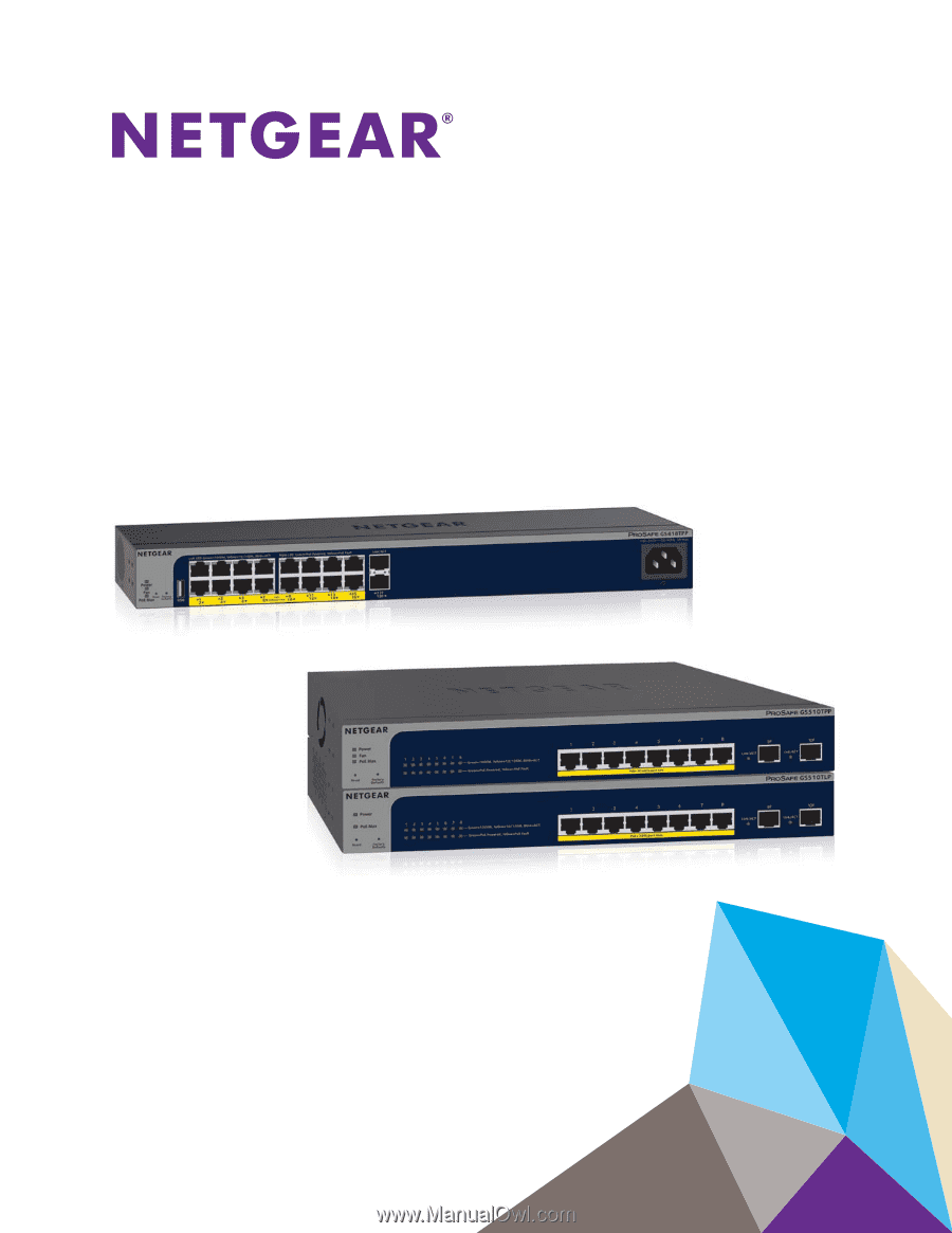
350 East Plumeria Drive
San Jose, CA 95134
USA
April 2017
202-11733-01
ProSAFE 8-Port or 16-Port
Gigabit Smart Managed Switch
with PoE+ and 2 SFP Ports
Models GS418TPP, GS510TLP, and GS510TPP
User Manual