Netgear GS418TPP User Manual - Page 220
Stateless Address AutoConfig Mode, Duplicate Address Detection Transmits
 |
View all Netgear GS418TPP manuals
Add to My Manuals
Save this manual to your list of manuals |
Page 220 highlights
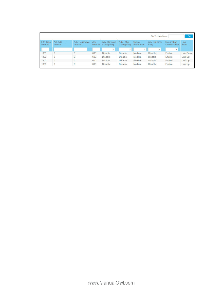
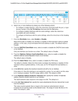
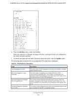
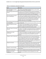
ProSAFE 8-Port or 16-Port Gigabit Smart Managed Switch Model GS418TPP, GS510TLP, and GS510TPP 6. Select one or more interfaces by taking one of the following actions: • To configure a single interface, select the check box associated with the port, or type the port number in the Go To Interface field and click the Go button. • To configure multiple interfaces with the same settings, select the check box associated with each interface. • To configure all interfaces with the same settings, select the check box in the heading row. 7. From the IPv6 Mode menu, select Enable or Disable. When IPv6 mode is enabled, the interface is capable of IPv6 operation without a global address. In this case, an EUI-64-based link-local address is used. The default value is Disable. 8. From the DHCPv6 Client Mode menu, select to enable or disable the DHCPv6 client mode on an interface. Only one interface can function as a client. The default value is Disable. 9. From the Stateless Address AutoConfig Mode menu, select to enable or disable the stateless address autoconfiguration mode on an interface. The default value is Disable. 10. From the Admin Mode menu, select to enable or disable the IPv6 mode. The default is Disable. When the IPv6 mode is enabled, the interface is capable of IPv6 operation without a global address. In this case, an EUI-64-based link-local address is used. 11. In the MTU field, specify the maximum transmit unit (MTU) for an interface. If the value is 0, then this interface is not enabled for routing. It is not valid to set this value to 0 if routing is enabled. The MTU range 1280 to 1500. The default is 1500. 12. In the Duplicate Address Detection Transmits field, specify the number of duplicate address detection (DAD) transmits on an interface. The DAD transmits value must be in the range 0 to 600. The default is 1. 13. In the Life Time Interval field, specify the router advertisement life time interval that is sent from the interface. This value must be greater than or equal to the maximum advertisement interval. 0 means do not use the router as the default router. The range of router life time is 0 to 9000. The default is 1800. Configure Routing 220
-
 1
1 -
2
-
3
-
4
-
5
-
6
-
7
-
8
-
9
-
10
-
11
-
12
-
13
-
14
-
15
-
16
-
17
-
18
-
19
-
20
-
21
-
22
-
23
-
24
-
25
-
26
-
27
-
28
-
29
-
30
-
31
-
32
-
33
-
34
-
35
-
36
-
37
-
38
-
39
-
40
-
41
-
42
-
43
-
44
-
45
-
46
-
47
-
48
-
49
-
50
-
51
-
52
-
53
-
54
-
55
-
56
-
57
-
58
-
59
-
60
-
61
-
62
-
63
-
64
-
65
-
66
-
67
-
68
-
69
-
70
-
71
-
72
-
73
-
74
-
75
-
76
-
77
-
78
-
79
-
80
-
81
-
82
-
83
-
84
-
85
-
86
-
87
-
88
-
89
-
90
-
91
-
92
-
93
-
94
-
95
-
96
-
97
-
98
-
99
-
100
-
101
-
102
-
103
-
104
-
105
-
106
-
107
-
108
-
109
-
110
-
111
-
112
-
113
-
114
-
115
-
116
-
117
-
118
-
119
-
120
-
121
-
122
-
123
-
124
-
125
-
126
-
127
-
128
-
129
-
130
-
131
-
132
-
133
-
134
-
135
-
136
-
137
-
138
-
139
-
140
-
141
-
142
-
143
-
144
-
145
-
146
-
147
-
148
-
149
-
150
-
151
-
152
-
153
-
154
-
155
-
156
-
157
-
158
-
159
-
160
-
161
-
162
-
163
-
164
-
165
-
166
-
167
-
168
-
169
-
170
-
171
-
172
-
173
-
174
-
175
-
176
-
177
-
178
-
179
-
180
-
181
-
182
-
183
-
184
-
185
-
186
-
187
-
188
-
189
-
190
-
191
-
192
-
193
-
194
-
195
-
196
-
197
-
198
-
199
-
200
-
201
-
202
-
203
-
204
-
205
-
206
-
207
-
208
-
209
-
210
-
211
-
212
-
213
-
214
-
 215
215 -
 216
216 -
 217
217 -
 218
218 -
 219
219 -
 220
220 -
 221
221 -
 222
222 -
 223
223 -
 224
224 -
 225
225 -
226
-
227
-
228
-
229
-
230
-
231
-
232
-
233
-
234
-
235
-
236
-
237
-
238
-
239
-
240
-
241
-
242
-
243
-
244
-
245
-
246
-
247
-
248
-
249
-
250
-
251
-
252
-
253
-
254
-
255
-
256
-
257
-
258
-
259
-
260
-
261
-
262
-
263
-
264
-
265
-
266
-
267
-
268
-
269
-
270
-
271
-
272
-
273
-
274
-
275
-
276
-
277
-
278
-
279
-
280
-
281
-
282
-
283
-
284
-
285
-
286
-
287
-
288
-
289
-
290
-
291
-
292
-
293
-
294
-
295
-
296
-
297
-
298
-
299
-
300
-
301
-
302
-
303
-
304
-
305
-
306
-
307
-
308
-
309
-
310
-
311
-
312
-
313
-
314
-
315
-
316
-
317
-
318
-
319
-
320
-
321
-
322
-
323
-
324
-
325
-
326
-
327
-
328
-
329
-
330
-
331
-
332
-
333
-
334
-
335
-
336
-
337
-
338
-
339
-
340
-
341
-
342
-
343
-
344
-
345
-
346
-
347
-
348
-
349
-
350
-
351
-
352
-
353
-
354
-
355
-
356
-
357
-
358
-
359
-
360
-
361
-
362
-
363
-
364
-
365
-
366
-
367
-
368
-
369
-
370
-
371
-
372
-
373
-
374
-
375
-
376
-
377
-
378
-
379
-
380
-
381
-
382
-
383
-
384
-
385
-
386
-
387
-
388
-
389
-
390
-
391
-
392
-
393
-
394
-
395
-
396
-
397
-
398
-
399
-
400
-
401
-
402
-
403
-
404
-
405
-
406
-
407
-
408
-
409
-
410
-
411
-
412
-
413
-
414
-
415
-
416
-
417
-
418
-
419
-
420
-
421
-
422
-
423
-
424
-
425
-
426
-
427
-
428
-
429
-
430
-
431
-
432
-
433
-
434
-
435
-
436
-
437
-
438
-
439
-
440
-
441
-
442
-
443
-
444
-
445
-
446
-
447
-
448
-
449
-
450
-
451
-
452
-
453
-
454
-
455
-
456
-
457
-
458
 |
 |