Netgear GS418TPP User Manual - Page 444
VLAN Routing Interface Configuration Example, Con the Router IP
 |
View all Netgear GS418TPP manuals
Add to My Manuals
Save this manual to your list of manuals |
Page 444 highlights
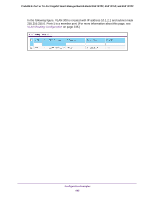
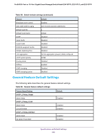
ProSAFE 8-Port or 16-Port Gigabit Smart Managed Switch Model GS418TPP, GS510TLP, and GS510TPP In this example, assume that Switch 1 became the root bridge for the MST instance 1, and Switch 2 became the root bridge for MST instance 2. Switch 3 supports hosts in the sales department (ports 1/0/1, 1/0/2, and 1/0/3) and in the HR department (ports 1/0/4 and 1/0/5). Switches 1 and 2 also include hosts in the sales and HR departments. The hosts connected from Switch 2 use VLAN 500, MST instance 2 to communicate with the hosts on Switch 3 directly. Likewise, hosts of Switch 1 use VLAN 300, MST instance 1 to communicate with the hosts on Switch 3 directly. The hosts use different instances of MSTP to effectively use the links across the switch. The same concept can be extended to other switches and more instances of MSTP. VLAN Routing Interface Configuration Example VLANs divide broadcast domains in a LAN environment. When hosts in one VLAN must communicate with hosts in another VLAN, the traffic must be routed between them. This is known as inter-VLAN routing. On the switch, it is accomplished by creating Layer 3 interfaces (switch virtual interfaces [SVI]). When a port is enabled for bridging (the default) rather than routing, all normal bridge processing is performed for an inbound packet, which is then associated with a VLAN. Its MAC destination address (MAC DA) and VLAN ID are used to search the MAC address table. If routing is enabled for the VLAN, and the MAC DA of an inbound unicast packet is that of the internal bridge-router interface, the packet is routed. An inbound multicast packet is forwarded to all ports in the VLAN, plus the internal bridge-router interface, if it was received on a routed VLAN. Since a port can be configured to belong to more than one VLAN, VLAN routing might be enabled for all of the VLANs on the port, or for a subset. VLAN routing can be used to allow more than one physical port to reside on the same subnet. It could also be used when a VLAN spans multiple physical networks, or when additional segmentation or security is required. A port can be either a VLAN port or a router port, but not both. However, a VLAN port can be part of a VLAN that is itself a router port. Complete these steps to configure a switch to perform interVLAN routing: 1. Use the IP Configuration page to enable routing on the switch. For more information about this step, see Configure the Router IP on page 212. 2. Determine the IP addresses that you want to assign to the VLAN interface on the switch. For the switch to be able to route between the VLANs, the VLAN interfaces must be configured with an IP address. When the switch receives a packet destined for another subnet/VLAN, the switch looks at the routing table to determine where to forward the packet. The packet is then passed to the VLAN interface of the destination. It is then sent to the port where the end device is attached. 3. Use the VLAN Routing Wizard page to create a routing VLAN, configure the IP address and subnet mask, and add the member ports. For more information about this step, see Use the VLAN Static Routing Wizard on page 233. Configuration Examples 444
-
 1
1 -
2
-
3
-
4
-
5
-
6
-
7
-
8
-
9
-
10
-
11
-
12
-
13
-
14
-
15
-
16
-
17
-
18
-
19
-
20
-
21
-
22
-
23
-
24
-
25
-
26
-
27
-
28
-
29
-
30
-
31
-
32
-
33
-
34
-
35
-
36
-
37
-
38
-
39
-
40
-
41
-
42
-
43
-
44
-
45
-
46
-
47
-
48
-
49
-
50
-
51
-
52
-
53
-
54
-
55
-
56
-
57
-
58
-
59
-
60
-
61
-
62
-
63
-
64
-
65
-
66
-
67
-
68
-
69
-
70
-
71
-
72
-
73
-
74
-
75
-
76
-
77
-
78
-
79
-
80
-
81
-
82
-
83
-
84
-
85
-
86
-
87
-
88
-
89
-
90
-
91
-
92
-
93
-
94
-
95
-
96
-
97
-
98
-
99
-
100
-
101
-
102
-
103
-
104
-
105
-
106
-
107
-
108
-
109
-
110
-
111
-
112
-
113
-
114
-
115
-
116
-
117
-
118
-
119
-
120
-
121
-
122
-
123
-
124
-
125
-
126
-
127
-
128
-
129
-
130
-
131
-
132
-
133
-
134
-
135
-
136
-
137
-
138
-
139
-
140
-
141
-
142
-
143
-
144
-
145
-
146
-
147
-
148
-
149
-
150
-
151
-
152
-
153
-
154
-
155
-
156
-
157
-
158
-
159
-
160
-
161
-
162
-
163
-
164
-
165
-
166
-
167
-
168
-
169
-
170
-
171
-
172
-
173
-
174
-
175
-
176
-
177
-
178
-
179
-
180
-
181
-
182
-
183
-
184
-
185
-
186
-
187
-
188
-
189
-
190
-
191
-
192
-
193
-
194
-
195
-
196
-
197
-
198
-
199
-
200
-
201
-
202
-
203
-
204
-
205
-
206
-
207
-
208
-
209
-
210
-
211
-
212
-
213
-
214
-
215
-
216
-
217
-
218
-
219
-
220
-
221
-
222
-
223
-
224
-
225
-
226
-
227
-
228
-
229
-
230
-
231
-
232
-
233
-
234
-
235
-
236
-
237
-
238
-
239
-
240
-
241
-
242
-
243
-
244
-
245
-
246
-
247
-
248
-
249
-
250
-
251
-
252
-
253
-
254
-
255
-
256
-
257
-
258
-
259
-
260
-
261
-
262
-
263
-
264
-
265
-
266
-
267
-
268
-
269
-
270
-
271
-
272
-
273
-
274
-
275
-
276
-
277
-
278
-
279
-
280
-
281
-
282
-
283
-
284
-
285
-
286
-
287
-
288
-
289
-
290
-
291
-
292
-
293
-
294
-
295
-
296
-
297
-
298
-
299
-
300
-
301
-
302
-
303
-
304
-
305
-
306
-
307
-
308
-
309
-
310
-
311
-
312
-
313
-
314
-
315
-
316
-
317
-
318
-
319
-
320
-
321
-
322
-
323
-
324
-
325
-
326
-
327
-
328
-
329
-
330
-
331
-
332
-
333
-
334
-
335
-
336
-
337
-
338
-
339
-
340
-
341
-
342
-
343
-
344
-
345
-
346
-
347
-
348
-
349
-
350
-
351
-
352
-
353
-
354
-
355
-
356
-
357
-
358
-
359
-
360
-
361
-
362
-
363
-
364
-
365
-
366
-
367
-
368
-
369
-
370
-
371
-
372
-
373
-
374
-
375
-
376
-
377
-
378
-
379
-
380
-
381
-
382
-
383
-
384
-
385
-
386
-
387
-
388
-
389
-
390
-
391
-
392
-
393
-
394
-
395
-
396
-
397
-
398
-
399
-
400
-
401
-
402
-
403
-
404
-
405
-
406
-
407
-
408
-
409
-
410
-
411
-
412
-
413
-
414
-
415
-
416
-
417
-
418
-
419
-
420
-
421
-
422
-
423
-
424
-
425
-
426
-
427
-
428
-
429
-
430
-
431
-
432
-
433
-
434
-
435
-
436
-
437
-
438
-
 439
439 -
 440
440 -
 441
441 -
 442
442 -
 443
443 -
 444
444 -
 445
445 -
 446
446 -
 447
447 -
 448
448 -
 449
449 -
450
-
451
-
452
-
453
-
454
-
455
-
456
-
457
-
458
 |
 |
