Netgear GS418TPP User Manual - Page 443
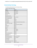
Switch 1, Enable, STP Status, Apply, Fast Link, MST ID, Priority, VLAN ID, Con VLAN, Settings
 |
View all Netgear GS418TPP manuals
Add to My Manuals
Save this manual to your list of manuals |
Page 443 highlights
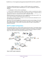
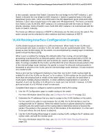
ProSAFE 8-Port or 16-Port Gigabit Smart Managed Switch Model GS418TPP, GS510TLP, and GS510TPP Perform the following procedures on each switch to configure MSTP: 1. On the VLAN Configuration page, create VLANs 300 and 500 (see Configure VLAN Settings on page 134). 2. On the VLAN Membership page, include ports 1/0/1-1/0/8 as tagged (T) or untagged (U) members of VLAN 300 and VLAN 500 (see Configure VLAN Settings on page 134). 3. On the STP Configuration page, enable the Spanning Tree State option (see Configure STP Settings on page 159). Use the default values for the rest of the STP configuration settings. By default, the STP operation mode is MSTP and the configuration name is the switch MAC address. 4. On the CST Configuration page, set the bridge priority value for each of the three switches to force Switch 1 to be the root bridge: • Switch 1. 4096 • Switch 2. 12288 • Switch 3. 20480 Note: Bridge priority values are multiples of 4096. If you do not specify a root bridge and all switches are assigned the same bridge priority value, the switch with the lowest MAC address is elected as the root bridge (see Configure CST Settings on page 161). 5. On the CST Port Configuration page, select ports 1/0/1-1/0/8 and select Enable from the STP Status menu (see Configure CST Port Settings on page 162). 6. Click the Apply button. 7. Select ports 1/0/1-1/0/5 (edge ports), and select Enable from the Fast Link menu. Since the edge ports are not at risk for network loops, ports with Fast Link enabled transition directly to the forwarding state. 8. Click the Apply button. You can use the CST Port Status page to view spanning tree information about each port. 9. On the MST Configuration page, create a MST instances with the following settings: • MST ID. 1 • Priority. Use the default (32768) • VLAN ID. 300 For more information, see View Rapid STP Information on page 166. 10. Click the Add button. 11. Create a second MST instance with the following settings • MST ID. 2 • Priority. 49152 • VLAN ID. 500 12. Click the Add button. Configuration Examples 443
-
 1
1 -
2
-
3
-
4
-
5
-
6
-
7
-
8
-
9
-
10
-
11
-
12
-
13
-
14
-
15
-
16
-
17
-
18
-
19
-
20
-
21
-
22
-
23
-
24
-
25
-
26
-
27
-
28
-
29
-
30
-
31
-
32
-
33
-
34
-
35
-
36
-
37
-
38
-
39
-
40
-
41
-
42
-
43
-
44
-
45
-
46
-
47
-
48
-
49
-
50
-
51
-
52
-
53
-
54
-
55
-
56
-
57
-
58
-
59
-
60
-
61
-
62
-
63
-
64
-
65
-
66
-
67
-
68
-
69
-
70
-
71
-
72
-
73
-
74
-
75
-
76
-
77
-
78
-
79
-
80
-
81
-
82
-
83
-
84
-
85
-
86
-
87
-
88
-
89
-
90
-
91
-
92
-
93
-
94
-
95
-
96
-
97
-
98
-
99
-
100
-
101
-
102
-
103
-
104
-
105
-
106
-
107
-
108
-
109
-
110
-
111
-
112
-
113
-
114
-
115
-
116
-
117
-
118
-
119
-
120
-
121
-
122
-
123
-
124
-
125
-
126
-
127
-
128
-
129
-
130
-
131
-
132
-
133
-
134
-
135
-
136
-
137
-
138
-
139
-
140
-
141
-
142
-
143
-
144
-
145
-
146
-
147
-
148
-
149
-
150
-
151
-
152
-
153
-
154
-
155
-
156
-
157
-
158
-
159
-
160
-
161
-
162
-
163
-
164
-
165
-
166
-
167
-
168
-
169
-
170
-
171
-
172
-
173
-
174
-
175
-
176
-
177
-
178
-
179
-
180
-
181
-
182
-
183
-
184
-
185
-
186
-
187
-
188
-
189
-
190
-
191
-
192
-
193
-
194
-
195
-
196
-
197
-
198
-
199
-
200
-
201
-
202
-
203
-
204
-
205
-
206
-
207
-
208
-
209
-
210
-
211
-
212
-
213
-
214
-
215
-
216
-
217
-
218
-
219
-
220
-
221
-
222
-
223
-
224
-
225
-
226
-
227
-
228
-
229
-
230
-
231
-
232
-
233
-
234
-
235
-
236
-
237
-
238
-
239
-
240
-
241
-
242
-
243
-
244
-
245
-
246
-
247
-
248
-
249
-
250
-
251
-
252
-
253
-
254
-
255
-
256
-
257
-
258
-
259
-
260
-
261
-
262
-
263
-
264
-
265
-
266
-
267
-
268
-
269
-
270
-
271
-
272
-
273
-
274
-
275
-
276
-
277
-
278
-
279
-
280
-
281
-
282
-
283
-
284
-
285
-
286
-
287
-
288
-
289
-
290
-
291
-
292
-
293
-
294
-
295
-
296
-
297
-
298
-
299
-
300
-
301
-
302
-
303
-
304
-
305
-
306
-
307
-
308
-
309
-
310
-
311
-
312
-
313
-
314
-
315
-
316
-
317
-
318
-
319
-
320
-
321
-
322
-
323
-
324
-
325
-
326
-
327
-
328
-
329
-
330
-
331
-
332
-
333
-
334
-
335
-
336
-
337
-
338
-
339
-
340
-
341
-
342
-
343
-
344
-
345
-
346
-
347
-
348
-
349
-
350
-
351
-
352
-
353
-
354
-
355
-
356
-
357
-
358
-
359
-
360
-
361
-
362
-
363
-
364
-
365
-
366
-
367
-
368
-
369
-
370
-
371
-
372
-
373
-
374
-
375
-
376
-
377
-
378
-
379
-
380
-
381
-
382
-
383
-
384
-
385
-
386
-
387
-
388
-
389
-
390
-
391
-
392
-
393
-
394
-
395
-
396
-
397
-
398
-
399
-
400
-
401
-
402
-
403
-
404
-
405
-
406
-
407
-
408
-
409
-
410
-
411
-
412
-
413
-
414
-
415
-
416
-
417
-
418
-
419
-
420
-
421
-
422
-
423
-
424
-
425
-
426
-
427
-
428
-
429
-
430
-
431
-
432
-
433
-
434
-
435
-
436
-
437
-
 438
438 -
 439
439 -
 440
440 -
 441
441 -
 442
442 -
 443
443 -
 444
444 -
 445
445 -
 446
446 -
 447
447 -
 448
448 -
449
-
450
-
451
-
452
-
453
-
454
-
455
-
456
-
457
-
458
 |
 |