Sony XVS-7000 Users Guide
Sony XVS-7000 Manual
 |
View all Sony XVS-7000 manuals
Add to My Manuals
Save this manual to your list of manuals |
Sony XVS-7000 manual content summary:
- Sony XVS-7000 | Users Guide - Page 1
-9200 XZS-9550 XZS-8540 XZS-7530 ICP-X7000 MKS-X7019 MKS-X7026 MKS-X7040 MKS-X2700 XVS-8000 XKS-S8110 XKS-C9111 XKS-S9167 XKS-C8166 XKS-8460 XZS-9510 XZS-8200 XZS-8550 XZS- XZS-8530 XZS-7520 MKS-X7018 MKS-X7024 MKS-X7035 User's Guide [English] Software Version 3.4 and Later 1st Edition (Revised 10) - Sony XVS-7000 | Users Guide - Page 2
TO USERS © 2015, 2016, 2017, 2018, 2019, 2020 Sony Corporation. All rights reserved. This manual or the software described herein, in whole or in part, may not be reproduced, translated or reduced to any machine readable form without prior written approval from Sony Corporation. SONY CORPORATION - Sony XVS-7000 | Users Guide - Page 3
in Version 3.4 The functions newly supported in XVS-9000/8000/7000/ 6000 System Ver. 3.4 are as follows. operation and menu settings are disabled. For details about the timing and version for support, contact your Sony service or sales representative. DME channels 5 to 8 • DME channel 5 to 8 - Sony XVS-7000 | Users Guide - Page 4
in Version 3.4 3 Functions and Operations Not Supported in Version 3.4 3 Chapter 1 Overview Introduction 16 61 Shutting Down the Switcher System...........62 Power Supply and Connector Section .... 63 XVS-9000/8000/7000/6000 Multi Format Switcher 63 Control Panel 69 MKS-X7011 Menu Panel 70 - Sony XVS-7000 | Users Guide - Page 5
91 Setting the Transition Rate 91 Pattern Limit 93 Executing an Auto Transition 94 Executing a Transition with the Fader Lever (Manual Transition 95 Auto/Manual Transition Combination ........95 Non-Sync State 95 Fader Lever Operation in Bus Fixed Mode 96 Split Fader 97 Transition Preview 98 - Sony XVS-7000 | Users Guide - Page 6
Snapshots 166 DME Wipe Snapshot Operations (Flexi Pad Control Block 166 DME Wipe Snapshot Operations (Menu 166 Creating User Programmable DME Patterns 166 User Programmable DME Transition Mode 166 Chapter 7 Frame Memory Overview 169 Frame Memory Operations 171 Preparations 171 Frame Memory - Sony XVS-7000 | Users Guide - Page 7
Displaying a List of Transition Rates and Changing the Settings 189 Setting the AUX Mix Transition Rate.......190 Aux Menu 190 Setting the Color Corrector for an AUX Bus 190 Status Menu 192 Router Menu 193 Destination Input List Display 193 Switching the Source for a Destination.....193 Video - Sony XVS-7000 | Users Guide - Page 8
Contrast Settings 243 Mosaic Settings 243 Sketch Settings 244 Metal Settings 245 Dim and Fade Settings 245 Glow Settings 245 Mask Settings 246 Freeze Settings 247 Applying Special Effects (Nonlinear Effect Settings 248 Wave Settings 248 Mosaic Glass Settings 250 Flag Settings 250 Twist - Sony XVS-7000 | Users Guide - Page 9
Keyframe Loop (Repeated Execution of a Specified Range 311 Undoing an Edit Operation 313 Duration Mode Setting 313 Transition Mode Settings for User Programmable DME 313 Time Settings 316 Setting the Keyframe Duration 316 Setting the Effect Duration 316 Delay Setting 316 Path Settings 317 - Sony XVS-7000 | Users Guide - Page 10
Chapter 14 Utility/Shotbox Utility Overview 337 Utility Execution 337 Utility Execution (Menu Panel 337 Utility Execution (Utility/Shotbox Control Block 338 Utility Execution (Cross-Point Control Block 338 Shotbox Overview 339 Shotbox Register Creation 340 Shotbox Register Creation (Numeric - Sony XVS-7000 | Users Guide - Page 11
Network Interface Settings .....388 Setting the Network Connector Board Service Port 388 Configuring a Network Interface 388 Setting the Network Recalling Setup Data 398 Selecting the Startup State 398 Saving User-Defined Settings 399 Restoring Initial Status File Settings .........399 Reset - Sony XVS-7000 | Users Guide - Page 12
the AUX Bus Operation Mode .....417 Setting the Router Operation Mode ..........417 Settings Relating to Button Assignment 419 Assigning Functions to User Preference Buttons 419 Assigning a Function to a Memory Recall Button in the Utility/Shotbox Control Block 423 Assigning Functions to Cross - Sony XVS-7000 | Users Guide - Page 13
Relating to Switcher Configuration 439 Adjusting the Reference Phase 439 Specifying the Video Switching Timing ...439 Setting the Operation Mode 439 Setting User Regions 441 Assigning PGM/PST Logically to an M/E 441 Setting DME Channel Assignments..........441 Setting the Side Flag Material and - Sony XVS-7000 | Users Guide - Page 14
511 Shotbox Menu 512 File Menu 512 Engineering Setup Menu 514 Diag Menu 519 Menus Recalled by Pressing a Button Twice 520 XVS-9000/8000/7000/6000 System Configuration Comparison 523 4K Format Restrictions 525 Resource Sharing Configuration Operations 526 File Manager 530 Preparations 530 - Sony XVS-7000 | Users Guide - Page 15
Frame Memory Import Menu Operations 531 Resource Share Menu Operations 532 Simple Connection of the MKS-8080/8082 AUX Bus Remote Panel 533 Procedure for Simple Connection 533 Setting Status of the MKS-8080/8082 in Simple Connection 534 Network AUX Remote Panel 535 Macro File Editing Rules 536 - Sony XVS-7000 | Users Guide - Page 16
XKS-8475 DME Board XKS-8470 HD DME Board Terms used in this manual • XVS-9000 • Switcher • Multi format switcher • XVS-8000 • Switcher • Multi format switcher • XVS-7000 • Switcher • Multi format switcher • XVS-6000 • Switcher • Multi format switcher • ICP-X7000 • Control panel • Integrated control - Sony XVS-7000 | Users Guide - Page 17
The XVS-9000/8000/7000/6000 Multi Format Switcher system is an extensible, high performance, multifunctionality switcher system that supports 4K video creation and networked media interface (NMI) input/ output. The following are some of the principal features of this system. 4K format support 4K - Sony XVS-7000 | Users Guide - Page 18
Main Functions Image Creation Transitions Switching from the current video feed to a new video feed is referred to as a transition. Switching a background video or key insertion/removal can be performed, depending on the transition. The method for switching video feeds (transition type) can be set, - Sony XVS-7000 | Users Guide - Page 19
Image Data Management and Operation Keyframes This function loads the conditions of the video at a point in time as data which can then be recalled to reproduce the same conditions. By arranging multiple keyframes on the time axis (timeline) and interpolating between successive keyframes, you can - Sony XVS-7000 | Users Guide - Page 20
Switcher setup (Switcher) For details, see "Switcher Setup" (page 439). DME setup (DME) For details, see "DME Setup" (page 472). DCU setup (DCU) For details, see "DCU Setup" (page 473). Router/tally setup (Router/Tally) For details, see "Router Interface and Tally Setup" (page 484). 20 - Sony XVS-7000 | Users Guide - Page 21
Panel 2 Chapter Names and Functions of Parts of the Control Panel The number of M/Es and number of DME channels supported by the XVS-9000, XVS-8000, XVS-7000, and XVS-6000 are different. Some button operations and menu settings for functions relating to M/Es and DMEs may be unavailable, depending - Sony XVS-7000 | Users Guide - Page 22
4M/E configuration example using 36-button modules for cross-point control block and AUX bus control block M/E-2 bank M/E-1 bank AUX bus control block (page 46) Menu panel (page 50) Key control block (page 36) Device control block (page 40) Utility/shotbox control block (page 45) Cross-point - Sony XVS-7000 | Users Guide - Page 23
1st row 2nd row b Display c Cross-point indicators 3rd row 4th row a Button rows d Cross-point pad a Button rows Used as cross-point buttons for selecting signals and functions. The 1st row buttons can also be used as 2nd row delegation buttons (key/AUX bus delegation mode). Name 1st row - Sony XVS-7000 | Users Guide - Page 24
Name 3rd row 4th row Description • Selects background A bus signal. • Selects the utility 1 bus signal while the [UTIL] button of the cross-point pad is pressed (utility bus mode). c) • Selects the bus signal or utility/ shotbox function b) selected by a delegation button on the crosspoint pad when - Sony XVS-7000 | Users Guide - Page 25
Inhibiting operation of a cross-point button row (protect function) To inhibit operation of buttons on the 1st to 4th rows, press the [ROW-1 PROT] to [ROW-4 PROT] buttons on the cross-point pad, turning them on. Inhibiting operation of a cross-point button row (inhibit function) To inhibit operation - Sony XVS-7000 | Users Guide - Page 26
For details, see "Configuring the Cross-Point Pad" (page 433). Use the following buttons to navigate the cross-point pad pages. • [HOME] button: Displays the HOME page configured in the Setup menu. • [ - Sony XVS-7000 | Users Guide - Page 27
Button name a) Description XPTHLD A XPTHLD B Sets cross-point hold for the background A or B bus. XPTHLD KEY1 to XPTHLD KEY8 Sets cross-point hold key 1 to 8 buses. XPTHLD UTIL1 XPTHLD UTIL2 (XPTHLD UTL1, XPTHLD UTL2) Sets cross-point hold for the utility 1 and 2 buses. XPTHLD DME EXT Sets - Sony XVS-7000 | Users Guide - Page 28
To assign a bus/function to the 1st row to 4th row, use the delegation buttons on the cross-point pad. Notes • When a key bus is assigned and a cross-point button is pressed, a key fill signal is selected. While a key bus delegation button is pressed, you can select a key fill signal on the 1st row - Sony XVS-7000 | Users Guide - Page 29
Transition Control Block The transition control block is used to execute transitions. It supports common transitions and independent key transition. a Display d Independent key transition execution section b Transition settings section b Transition settings section c Transition execution section - Sony XVS-7000 | Users Guide - Page 30
Button name KEY1/5, KEY2/6, KEY3/7, KEY4/8, ADD, SHIFT KEY PRIOR (key priority) ALL PRIOR SET (priority set) Description (Assignment in the Setup menu is required.) • Press the [KEY1/5] button, turning it on, to insert or remove key 1 using the next transition. Press the [SHIFT] button, turning it - Sony XVS-7000 | Users Guide - Page 31
For details about operation of external devices, see "Control of VTRs and Disk Recorders" (page 286). c Transition execution section This section is used to execute transitions and check the progress of the transition. d Independent key transition execution section This section executes independent - Sony XVS-7000 | Users Guide - Page 32
Transition Control Block (Simple Type) The simple-type transition control block is used to execute background transitions. For details about transition types, see "Transition Type" (page 84). a Transition settings section When multi-program mode is selected, there may be cases in which two or - Sony XVS-7000 | Users Guide - Page 33
MCRO TAKE (macro take) button (Assignment in the Setup menu is required.) Executes a macro take operation. This can only be assigned to the four buttons on the left. External device operation buttons (Assignment in the Setup menu is required.) These buttons are used to control playback, stop, and - Sony XVS-7000 | Users Guide - Page 34
a Independent key transition display section b KEY ON buttons b KEY ON buttons c AUTO TRANS buttons a Independent key transition display section The following information is displayed for the assigned key on the [KEY ON] buttons. • Key material name (key source name when a key source is selected - Sony XVS-7000 | Users Guide - Page 35
a Mode selection buttons These buttons select the operation mode of the Flexi Pad control block. Press a mode selection button to change the memory recall section to the display for the selected operation mode. You can change the assignment of mode selection buttons in the Setup menu. For details, - Sony XVS-7000 | Users Guide - Page 36
Button name BANK SEL (bank select) Description Switches the memory recall section to numeric keypad mode for entering bank numbers. Enter a bank number and press the [ENTER] button to switch the memory recall section to the register display for the selected bank. Key Control Block The key control - Sony XVS-7000 | Users Guide - Page 37
b DME channel selection buttons These select the DME channel to assign to a key. When the [TRANS] or [SUB TRANS] delegation button is selected, the DME channel used by the DME wipe is displayed. You can select the DME channel to be used beforehand when a DME wipe is selected as the transition type. - Sony XVS-7000 | Users Guide - Page 38
Button name OVERRIDE TRACE MON (monitor) PROC KEY (processed key) FM FEED (frame memory feed) SHOW KEY Description Assigns a DME channel assigned to another key/bus to the currently selected key (override function). Press and hold the [OVERRIDE] button and press the target DME channel button to - Sony XVS-7000 | Users Guide - Page 39
Key Fader Control Block The key fader control block is used to execute independent key transitions and for key snapshot operations. a Key delegation buttons b Display c Key snapshot operation buttons d Independent key transition type selection buttons e Independent key transition execution section - Sony XVS-7000 | Users Guide - Page 40
For details about transition types, see "Transition Type" (page 84). e Independent key transition execution section This section executes independent key transitions. KEY ON buttons Fader lever Transition indicator AUTO TRANS buttons Name Fader lever Transition indicator KEY ON buttons AUTO - Sony XVS-7000 | Users Guide - Page 41
Button name M/E1 to M/E5, P/P DME MENU RUN CTRL (run control) DEV (device) Description • Switches to resizer operation mode. • You can select more than one button. The first selected button becomes the reference, and is lit green. Subsequent selected buttons are lit amber. Switches to three- - Sony XVS-7000 | Users Guide - Page 42
Button name Description CTR (center) • When the [CTR] is pressed once: Adjusts the two-dimensional transform setting values to the closest detent positions. • When the [CTR] button is pressed twice, or is pressed once while pressing the [SHIFT] button: Returns the two-dimensional transform - Sony XVS-7000 | Users Guide - Page 43
e Trackball This adjusts the parameters of items selected using the operation buttons. Resizer operation mode Moves the key, to which the resizer is applied, in the Xaxis and Y-axis directions, changes the X/Y aspect ratio, rotates the keys around the X-axis and Y-axis, and changes the border width - Sony XVS-7000 | Users Guide - Page 44
Selection Buttons in the Numeric Keypad Control Block" (page 409) and "Recalling regions to edit (menu)" (page 307). Button name M/E1 to M/E5, P/P USER 1 to USER 8 DME1 to DME4 DEV1 to DEV12 P-BUS GPI RTR MCRO MASTR Description Selects the M/E-1 to M/E-5 and PGM/PST regions. Selects the USER1 to - Sony XVS-7000 | Users Guide - Page 45
the [TRIM] button. Button name ENTER Description Confirms an entered value or selected attribute. Note The [GPI ENBL] button function is not supported. The numeric keypad buttons on the numeric keypad control block are also used when entering numeric values in conjunction with other operations - Sony XVS-7000 | Users Guide - Page 46
Button name BANK1 to BANK20 TRANS RATE1 to TRANS RATE3 (transition rate 1 to transition rate 3) KF MCRO EDIT (keyframe macro edit) Description (Assignment of the [BANK7] to [BANK20] buttons in the Setup menu is required.) Switches the memory recall buttons to the function recall mode set in the - Sony XVS-7000 | Users Guide - Page 47
1st row 2nd row b Display c Cross-point indicators 3rd row 4th row a Button rows d Cross-point pad AUX bus operation mode Used for bus signal selection. For details about assignable buses, see "Bus Selection" (page 77). a Button rows The 1st row/2nd row are used as bus selection delegation - Sony XVS-7000 | Users Guide - Page 48
For details, see "Colors of lit cross-point buttons" (page 82). SHIFT button The [SHIFT] button function is assigned to the button on the right-hand end, and is used to toggle between the shifted and unshifted states of the button row. The operation of the [SHIFT] button in second delegation mode - Sony XVS-7000 | Users Guide - Page 49
Button name a) Description NEXT (>> XXX) Displays the next page of the crosspoint pad. XXX = page name (up to 12 characters) Row-n Assign Status (XXX) Displays the bus/function names assigned to the 1st row to 4th row. n = 1 to 4 XXX = bus/function name b) Current Page Status (PAGE 1 XXX to - Sony XVS-7000 | Users Guide - Page 50
The 1st row and 2nd row can select different destinations (second delegation mode) by pressing the [2ND DELG] button on the cross-point pad, turning it on. Name 1st row 2nd row 3rd row 4th row Description When the [2ND DELG] button is lit: Selects a destination to assign in the 3rd row. When the [ - Sony XVS-7000 | Users Guide - Page 51
the assignment of mode top menu selection buttons in the Setup menu. For details, see "Setting Menu Panel Button Assignments" (page 411). b User preference buttons These buttons recall functions and menus assigned to the buttons. You can assign the following functions to the [PREFS 1] to [PREFS 16 - Sony XVS-7000 | Users Guide - Page 52
Names and Functions of Parts of the Menu Screen Overview All detailed settings for basic operations such as transitions, keys, wipes, and DME are made in menus. In addition, system management, data management, and setup are all performed using menu operations. The menu is operated using the menu - Sony XVS-7000 | Users Guide - Page 53
qs b button and B button 5 Status area 2 Menu page number button 1 Menu title button 6 Function button area 7 Parameter group button 0 Keyframe status qa Default Recall button 3 VF buttons 4 HF buttons 9 Previous page button 8 Parameter setting buttons a Menu title button This button displays - Sony XVS-7000 | Users Guide - Page 54
Depending on the selected item, the content displayed on the menu screen and the HF button indicators change. d HF buttons These indicate the smaller subdivisions (3rd level) of the menu. Depending on the selected item, the menu indications change. Depending on the function, whenever any button is - Sony XVS-7000 | Users Guide - Page 55
Top Menu Window a Top menu selection buttons Displays the selected menu. b Add Favorite button This button registers the currently displayed menu in the shortcut menu (see page 60). c Close button This button closes the top menu window. d Page number entry section Enter a page number and press [ - Sony XVS-7000 | Users Guide - Page 56
Numeric Keypad Window 1Item display 2 Max./min. value indication 3Input display 4Close button 5TC button 6- button 7Clear button 8Trim button 9Enter button a Item display This displays the name of the parameter being set using the numeric keypad window. b Max./min. value indication This displays the - Sony XVS-7000 | Users Guide - Page 57
a Item display b Input display c Close button d Caps Lock button e Shift button f BS button g Line feed button h Enter button i Space button k Del button n Right button j Clear button m Left button l Home button o End button a Item display This is the name of the parameter being set. b - Sony XVS-7000 | Users Guide - Page 58
Color Palette Window When parameters are assigned a combination of luminance, saturation, and hue, pressing a parameter setting button displays the color palette window. a Color palette buttons b Operation buttons c Color display section d Numeric keypad control block a Color palette buttons - Sony XVS-7000 | Users Guide - Page 59
of screen) to select the 3rd level menu. 3 Press the appropriate function button within the function button area (center of screen). In this manual, menu selection operations are indicated as "1st level >2nd level >3rd level (menu page number)." Example: To select the Shortcut menu Home >Favorites - Sony XVS-7000 | Users Guide - Page 60
see "Menu Tree" (page 501). Notes • The default state varies depending on the initial status mode specified in the Setup menu. User: State configured by the user Factory: Factory default state For details, see "Power-On (Startup) State Selection" (page 397). • The horizontal (H) and vertical (V) of - Sony XVS-7000 | Users Guide - Page 61
the history in each menu. To choose the sub menu site, press the [SUB MENU SITE] button, assigned to a top menu selection button or user preference button on the menu panel, turning it on. For details about button assignment, see "Setting Menu Panel Button Assignments" (page 411). Shutting Down - Sony XVS-7000 | Users Guide - Page 62
Shutting Down the Switcher System Before turning the switcher system off, shut down the switcher, switcher control station, and menu using the following procedure. Note If the switcher system is configured with several switchers and control panels, shutting down the switcher control station will - Sony XVS-7000 | Users Guide - Page 63
Power Supply and Connector Section XVS-9000/8000/7000/6000 Multi Format Switcher Front view XVS-9000 XVS-8000 POWER A, B, C, D switch and status indicators POWER A, B, C, D, E, F switch and status indicators XVS-7000 XVS-6000 POWER A, B, C, D switch and status indicators POWER A, B switch - Sony XVS-7000 | Users Guide - Page 64
switch and status indicators (XVS-9000) POWER A, B, C, D switch and status indicators (XVS-8000/7000) POWER A, B switch and status indicators (XVS-6000) Turn the POWER input outside specified range • DC output outside specified range Rear view XVS-9000 b OUTPUT 1 to 80 connectors a INPUT 1 to 160 - Sony XVS-7000 | Users Guide - Page 65
XVS-8000 d DEDICATED INPUT 1 to 16 connectors e M/E DEDICATED OUTPUT 1 to 16 connectors f INPUT 1 to 160 connectors i FC OUTPUT 1 to 16 connectors j SPARE 1 to 4 connectors k MV OUTPUT 1 to 8 connectors XVS-7000 i FC OUTPUT 1 to 16 connectors j SPARE 1 to 4 connectors k MV OUTPUT 1 to 8 connectors - Sony XVS-7000 | Users Guide - Page 66
RJ-45 type: XKS-T8110, QSFP+ type: XKS-Q8111, QSFP28 type: XKS-C8111) XVS-8000: 1 to 160 connectors XVS-7000: 1 to 112 connectors XVS-6000: 1 to 64 connectors Up to 160 (XVS-8000), 112 (XVS-7000), and 64 (XVS-6000) serial digital video signals can be input. The number of connectors (slots) available - Sony XVS-7000 | Users Guide - Page 67
stations connected to an Ethernet switch. 1) For details about supported Ethernet switches, contact your Sony service or sales representative. For details about Ethernet switch connection, refer to the XVS-9000/8000/ 7000/6000 Installation Manual. q UTL LAN (utility LAN) connector (RJ-45 compliant - Sony XVS-7000 | Users Guide - Page 68
"Enabling/Disabling SDI Output Connectors" (page 404). Note On the XVS-9000, when the switcher signal format is 3840×2160P 2SI, if XKS-C9121N cannot be installed at the same time. • The XKS-C9121/XKS-C9121N supports both inputs and outputs (bidirectional). • On the XKS-C9111N/XKS-C9121N, input/ - Sony XVS-7000 | Users Guide - Page 69
Ethernet switch. The unit can operate without using an AC adaptor if connected to a PoE+ (Power over Ethernet Plus) compatible Ethernet switch. 1) 1) For details about supported PoE+ compatible Ethernet switches, contact your Sony service or sales representative. 69 - Sony XVS-7000 | Users Guide - Page 70
an AC adaptor if connected to a PoE+ (Power over Ethernet Plus) compatible Ethernet switch. 1) 1) For details about supported PoE+ compatible Ethernet switches, contact your Sony service or sales representative. DEVICE connector (USB 2.0 compliant, USB Type A) Connect to a USB flash drive. Used for - Sony XVS-7000 | Users Guide - Page 71
. Notes • If a status indicator is not lit when the POWER switch is turned on, there may be a problem with the power supply wiring. Turn the POWER switch off and contact your Sony service representative. • If a status indicator momentarily is lit red when the power supply is turned on, a tone may - Sony XVS-7000 | Users Guide - Page 72
Rear view MKS-X2700 h SERIAL TALLY 1 and 2 connectors g REMOTE 1 to 6 connectors a U terminal b -AC IN A and B connectors MKS-X7700 j TALLY/GPI IN 1 to 34 connectors i TALLY/GPI OUT 1 to 36 connectors c REF IN connectors d UTIL connector e MVS connector f S-BUS connector g REMOTE 1 to 6 - Sony XVS-7000 | Users Guide - Page 73
to 6 connectors, 1 to 4 connectors Connect to a device controlled using Sony 9-pin VTR, VDCP (Video Disk Communications Protocol), Odetics protocol, or P- connectors Outputs tally information generated by the switcher control station of the XVS system using a relay. It can also be used as a GPI output - Sony XVS-7000 | Users Guide - Page 74
Signal Selection and Transitions 3 Chapter Image Creation Operation Flow The switch from the current video feed (appearing on the switcher bank program monitor) to a new video feed is referred to as a transition. Select current background video The following illustration shows the flow of - Sony XVS-7000 | Users Guide - Page 75
Signal Selection You carry out signal selection with the cross-point buttons in the cross-point control block of the M/E bank or PGM/ PST bank, and the buttons in the AUX bus control block (AUX bus operation mode). Depending on the module used, each row has 36 buttons, 28 buttons, or 20 buttons. - Sony XVS-7000 | Users Guide - Page 76
, re-entry signals within the same switcher bank can be selected. Re-entry signal restrictions Up to four re-entry stages are supported. The following restrictions apply, depending on the signal format and M/E configuration, for re-entry signal selection. Signal format • 1080P • 3840×2160P • 720P - Sony XVS-7000 | Users Guide - Page 77
Bus Selection Each cross-point button row is shared by multiple buses. To assign a bus to the 1st row to 4th row cross-point buttons in the cross-point control block, press one of the bus delegation buttons in the cross-point pad, turning it on. To assign a bus to the 3rd row/4th row cross-point - Sony XVS-7000 | Users Guide - Page 78
Control block Bus name Cross-point control block: M/E-1 M/E-2 M/E-3 M/E-4 M/E-5 PGM/PST AUX1 bus to AUX48 bus Frame memory source 1 bus Frame memory source 2 bus DME1 video bus to DME4 video bus DME1 key bus to DME4 key bus AUX bus control block (AUX bus operation mode) AUX1 bus to AUX48 bus - Sony XVS-7000 | Users Guide - Page 79
, turning it on. You can change the bus assignments of the 1st row to 4th row in the Setup menu. The following bus assignments are supported. - Background A bus, B bus - Key 1 bus to key 8 bus The [UTIL] button operation can be set to hold mode or lock mode. For details, see "Setting - Sony XVS-7000 | Users Guide - Page 80
Cross-point control block button numbers SHIFT button 1, 2, 3, 4, ... 36, 37, 38, 39, ... (first numbers) (second numbers) ..., 33, 34, 35 ..., 68, 69, 70 SHIFT button On the M/E and PGM/PST banks, each cross-point button has two button numbers, and you use the [SHIFT] button to switch between - Sony XVS-7000 | Users Guide - Page 81
For details, see "Setting the AUX Bus Operation Mode" (page 417) and "Setting the [SHIFT] button operation mode" (page 414). When the [2ND DELG] button is not lit The bus selected by the delegation buttons in the 1st row or 2nd row is assigned to the 3rd row and 4th row. In the case of a 36-button - Sony XVS-7000 | Users Guide - Page 82
keys (1 to 8) to execute a transition. Note For details about the keys that can be used on each switcher bank in 4K format, see "Keys supported in 4K format" (page 107). Changing the background A background transition switches from the video selected on the background A bus (the current video) to - Sony XVS-7000 | Users Guide - Page 83
Inserting key when switching the background Key 1 Insert Remove Key 1 Key 2 Simultaneously inserting and removing keys Key 1 Transition Transition Key 2 Inserting and removing keys when switching the background Key 1 Key 2 Transition Key 2 Combining a background and key You can simultaneously - Sony XVS-7000 | Users Guide - Page 84
Transition Type Type Description Independent key transitions Mix The new video progressively Selectable fades in over the current video. The sum of the two video outputs is maintained at a constant, with the output of each at 50% at the mid- point of the transition (i.e., when the fader - Sony XVS-7000 | Users Guide - Page 85
For details about double-press operation settings of the [BKGD] button, see "Setting the Button and Fader Lever Operation Mode" (page 430). For details about settings of the [ALL] button, see "Setting the Operation Mode of the [ALL] Button in the Transition Control Block" (page 431). Note More than - Sony XVS-7000 | Users Guide - Page 86
1 Select the background video on the cross-point control block. Select the video to display before execution of the transition using the background A bus cross-point buttons, and the video to display after the transition using the background B bus cross-point buttons. 2 Select the transition type - Sony XVS-7000 | Users Guide - Page 87
) Next transition selection buttons PRIOR SET button KEY PRIOR button Transition control block Note Setting the key priority is not supported using the transition control block (simple type). Changing the key priority Key priority: 3, 1, 4, 2 Select [KEY1]. Key priority: 1, 3, 4, 2 1 Press and hold - Sony XVS-7000 | Users Guide - Page 88
To set the key priority of the keys for after the transition, open the M/E-1 >Misc >Next Key Priority menu (1174). 2 In the group, select the group to display at the front. The selected group button is lit green, indicating that the priority of the keys within the group can be set. 3 - Sony XVS-7000 | Users Guide - Page 89
Transition Type Selection For details about selecting the transition type on the transition control block, see "Basic Operation for Transitions" (page 84). Setting the Transition Type (Menu) You can select the transition type in the Misc >Transition menu for each switcher bank. This section - Sony XVS-7000 | Users Guide - Page 90
When a key is inserted Key The key is gradually removed. When, with a key inserted, a key is selected in the next transition Key Key state is preserved. When no key is selected. Key gradually fades in to the new video. When a key is selected in the next transition. The key is gradually removed. - Sony XVS-7000 | Users Guide - Page 91
, to the left of the fader lever is a transition indicator composed of multiple LEDs. This indicator shows the state of the transition, whether auto or manual, by which LEDs are lit. Note When a clip transition is selected as the transition type, it is not possible to set the transition rate. Frame - Sony XVS-7000 | Users Guide - Page 92
Setting the transition rate (Flexi Pad control block) TRANS RATE button TC button CLEAR button displaying a transition rate enables you to enter a transition rate using the numeric keypad control block. You can change the target that is displayed on the [TRANS RATE1] to [TRANS RATE3] buttons in the - Sony XVS-7000 | Users Guide - Page 93
] and [LIMIT SET] buttons are set on the transition control block (simple type) by default. Also, transition preview and cut operations are not supported. Setting the pattern limit with the fader lever 1 Move the fader lever to the position corresponding to a particular pattern size. Notes • First - Sony XVS-7000 | Users Guide - Page 94
2 Press the [LIMIT SET] button. This sets the current fader lever position as the pattern limit. Setting the pattern limit (menu) This section describes setting the pattern limit on the M/E-1 bank as an example. 1 Display the pattern limit setting menu. When the transition type is a wipe, open the - Sony XVS-7000 | Users Guide - Page 95
TRANS] button on the transition control block (simple type). Also, cut operations are not supported. Executing a Transition with the Fader Lever (Manual Transition) Using the fader lever, you can manually control the progress of the transition effect specified by the transition Moving the fader - Sony XVS-7000 | Users Guide - Page 96
fixed relationship between the position of the fader lever and the signal output on the background A bus and background B bus. When executing a manual transition, the fader lever must therefore always be moved in the directions shown in the following table according to the transition direction. This - Sony XVS-7000 | Users Guide - Page 97
type) is split into two by pressing the lock button to unlock the two fader levers for use as split faders. The split fader levers support the following buses. You can change the settings in the Setup menu. • Right fader lever: Background A bus (main) • Left fader lever: Background B bus The - Sony XVS-7000 | Users Guide - Page 98
in the following cases. - Transitions in progress - Multi-program mode - DSK mode - Bus fixed mode • Transition preview operations are not supported using the transition control block (simple type). There are three modes for a transition preview. Hold mode: Transition preview mode is enabled only - Sony XVS-7000 | Users Guide - Page 99
Independent Key Transitions Overview In addition to common transitions, it is possible to configure independent transitions on the keyers of the M/E banks and PGM/PST bank. These are called "independent key transitions." By carrying out an independent key transition in combination with a common - Sony XVS-7000 | Users Guide - Page 100
Example: When the independent key transition [AUTO TRANS] button is pressed later Wipe and mix progress simultaneously. Transition (wipe) The transitions continue until both are completed. Independent key transition (mix) Time offset execution If the [AUTO TRANS] buttons for the transition and - Sony XVS-7000 | Users Guide - Page 101
the transition control block. The same operations can also be performed using the independent key transition control block. Note Independent key transition operations are not supported using the transition control block (simple type). 101 - Sony XVS-7000 | Users Guide - Page 102
KEY5 ON to KEY8 ON buttons Independent key transition display section When the Keyframe Strobe effect is set, the effects are equivalent to operation using keyframes. In this case as well, cancel the unnecessary DME settings. Executing an independent key transition (key fader control block) - Sony XVS-7000 | Users Guide - Page 103
To insert or remove the key gradually with a mix or wipe, press the [AUTO TRANS] button for the corresponding key or operate the fader lever. Pressing the [AUTO TRANS] button executes the transition at the preset transition rate. To insert/remove the key instantaneously, press the [KEY ON] button - Sony XVS-7000 | Users Guide - Page 104
Setting the independent key transition rate (utility/shotbox control block and numeric keypad control block) If the independent key transition mode is set to [Independ], setting the transition rate while a key is not inserted will set the transition rate for key insertion, and setting the transition - Sony XVS-7000 | Users Guide - Page 105
mode • Memory recall buttons in the utility/shotbox control block • User preference buttons in the menu panel This section describes operation using 17 to 20 - 25 to 28 and 29 to 32 (XVS-8000/7000 only) - 37 to 40 and 41 to 44 (XVS-8000/7000 only) Executing an AUX mix transition Use the [AUX MIX - Sony XVS-7000 | Users Guide - Page 106
Delegation buttons AUX MIX button Note On the XKS-C9121N, outputs that are multiples of 8 minus 1 (7, 15, 23, and so on) are invalid because outputs 7 and 15 on each board cannot be used. For example, for a combination of output 5 (AUX1 bus) and output 7 (AUX2 bus), an AUX mix transition image - Sony XVS-7000 | Users Guide - Page 107
"key fill." The system component responsible for processing a key is referred to as a "keyer." Each M/E bank and the PGM/PST bank has eight keyers. Keys supported in 4K format The following keys can be used on each switcher bank. • 3840×2160P: Key 1 to key 4 • 3840×2160PsF: Key 1 to key 2 Key 3 and - Sony XVS-7000 | Users Guide - Page 108
Key Modifiers Edge modifiers You can apply borders and other modifiers to the edge of the key image. Type Normal Description Video This is the state with no key edge modifiers applied. Border Drop border Applies a border around the key. You can adjust the border width and density. You can - Sony XVS-7000 | Users Guide - Page 109
The edge fill may be either the signal from the dedicated color matte generator, or the signal currently selected on the utility 1 bus. In the case of an outline, there is no edge fill signal selection, because the key fill signal fills the outline, and the rest of the image remains as the - Sony XVS-7000 | Users Guide - Page 110
Key Setting Operations (Menu) When a key wipe pattern key is selected: Press [Pattern Select] to open the M/E-1 >Key1 >Transition/Video Process >Wipe Adjust >Pattern Select menu (1117.2), and select a pattern and set modifiers (see page 150). There are two ways of making key settings: either using - Sony XVS-7000 | Users Guide - Page 111
5 Make the following settings as required. To invert the black and white of the key source: Press [Key Invert], turning it on. To adjust the horizontal position or key source width for a luminance key, linear key, color vector key, or chroma key: Press [Key Position], turning it on, and set the - Sony XVS-7000 | Users Guide - Page 112
- Key delegation buttons in the memory recall section on the Flexi Pad control block (key operation mode) • You can assign a key source bus delegation button to the 1st row or 2nd row of the AUX bus control block (AUX bus operation mode) in the Setup menu (see page 417). To select a video signal - Sony XVS-7000 | Users Guide - Page 113
can now adjust the key density (see page 110). 3 Press [Chroma Adjust]. The Chroma Adjust menu (1111.1) appears. 4 Execute auto chroma key. Make manual adjustments as necessary to obtain an optimum chroma key image (see page 114). 5 In the group, select the chroma key composition method - Sony XVS-7000 | Users Guide - Page 114
will be obtained by first carrying out adjustments with the auto chroma key function, then making any fine adjustments as required. The following manual adjustments are possible. Key active When disabled, only the foreground is output and you can make color cancel adjustments. Color cancel If the - Sony XVS-7000 | Users Guide - Page 115
adjusting the keying. When the key active function is disabled, only the foreground image appears. Disable key active when manually adjusting color cancel. 1 In the M/E-1 >Key1 >Type >Chroma Adjust menu (1111.1), press [Key Active], turning it on. 2 Set the following parameters. No. Parameter - Sony XVS-7000 | Users Guide - Page 116
No. Parameter Adjustment 1 Mixture Ratio of Y balance key Adjusting the window Enabling the window (see page 114) function allows you to adjust the detection range used to determine the key signal. When disabled, the default range is used for image adjustment. To adjust the window, adjustment of - Sony XVS-7000 | Users Guide - Page 117
No. Parameter Adjustment 3 Density Density • When separate edge is enabled The left, right, top, and bottom border or outline widths can be adjusted independently. The separate edge function is only available when luminance key, linear key, color vector key, or chroma key is selected as the key - Sony XVS-7000 | Users Guide - Page 118
8 To make separate fine adjustments to the positions of the left, right, top, and bottom of the key source, select [Fine Key] and set the following parameters. Parameter group [1/2] No. Parameter Adjustment 1 Top Key top edge position 2 Left Key left edge position 3 Right Key right edge - Sony XVS-7000 | Users Guide - Page 119
When selecting [Multi] and replicating the pattern No. Parameter Adjustment 1 H Multi Number of repetitions of pattern horizontally 2 V Multi Number of repetitions of pattern vertically 3 Invert Type Replication layout a) a) See page 147. When selecting [Aspect] and adjusting the pattern - Sony XVS-7000 | Users Guide - Page 120
4 Depending on the selection in step 3, set the following parameters. When [Box] is selected No. Parameter Adjustment 1 Top Position of top side 2 Left Position of left side 3 Right Position of right side 4 Bottom Position of bottom side 5 Soft Degree of softness of box When [ - Sony XVS-7000 | Users Guide - Page 121
that can be used and on the functions, depending on the switcher and signal format. For differences in functions by switcher, see "XVS-9000/ 8000/7000/6000 System Configuration Comparison" (page 523). For details about restrictions for 4K format, see "4K Format Restrictions" (page 525). • The number - Sony XVS-7000 | Users Guide - Page 122
• On the cross-point control block in key/AUX bus delegation mode, press the [DME UTIL1] button in the 1st row and select a signal using the cross-point buttons in the 2nd row. Notes • You can assign the DME utility 1 bus using the [UTIL] button on the cross-point pad of the crosspoint control block - Sony XVS-7000 | Users Guide - Page 123
Specifying the Key Output Destination Using a processed key keyer signal (external processed key) To select key fill and key source signals for a processed key keyer on the AUX bus or edit preview bus, press [Ext Proc Key] in the M/E-1 >Key1 >Processed Key menu (1116), turning it on. This assigns - Sony XVS-7000 | Users Guide - Page 124
Key Operations (Key Control Block) Setting buttons display section Delegation buttons Adjustment knobs Display The parameter assignment to the adjustment knob is canceled, and the selected setting button changes color from green to amber. Selecting the Bank and Keyer 1 Press the delegation button - Sony XVS-7000 | Users Guide - Page 125
When key wipe pattern key is selected No. Parameter Adjustment 1 SIZE Pattern size 2 SOFT Degree of edge softness 3 DENSITY Key density • On the cross-point control block, press a key bus delegation button on the cross-point pad and select a signal using the cross-point buttons. • On the - Sony XVS-7000 | Users Guide - Page 126
When using the selected key fill signal as the key source Press the [AUTO SEL] button and [SPLT] button simultaneously. When both buttons are off, Self mode is selected. Note When chroma key is selected as the key type, select Self mode. Key Adjustments (Key Control Block) You can make the - Sony XVS-7000 | Users Guide - Page 127
Setting the color cancel parameters No. Parameter 1 LUM 2 SAT 3 HUE 5 FILTER Adjustment Luminance Saturation Hue Filter coefficient Key Edge Modification Press the [PAGE] button to display the page 2/3 setting buttons. Press a key modifier button to select an edge type (see page 108). [BDR] - Sony XVS-7000 | Users Guide - Page 128
Assigning a DME to a key 1 Press the delegation button for the target bank (M/E1 to M/E5, P/P), turning it on. 2 Press the delegation button for the target keyer (KEY1 to KEY8), turning it on. 3 Using the DME channel selection buttons (DME1 to DME4), select the DME channel to use. The lit colors of - Sony XVS-7000 | Users Guide - Page 129
Using auto delegation To couple the selection of the buttons in the following control blocks so that the delegation selection switches automatically in the key control block, press the [AUTO DELEG] button, turning it on. • Transition control block: [KEY1] to [KEY8] buttons • Cross-point pad on the - Sony XVS-7000 | Users Guide - Page 130
2 Set the following parameters. Parameter group [1/2] No. Parameter Adjustment 1 Location X Horizontal key movement 2 Location Y Vertical key movement 3 Size Key reduction/enlargement 4 a) Rotation X Horizontal key rotation 4 b) Rotation Y Vertical key rotation 5 Perspective Perspective - Sony XVS-7000 | Users Guide - Page 131
Reducing, enlarging, rotating, and moving keys (device control block) Channel selection buttons FINE button Mode selection buttons LOC SIZE button X, Y, Z buttons RSZR ON button Z-ring ROT button Trackball ASP PERS button Device control block (trackball) 1 Press the [M/E1] button. The [M/ - Sony XVS-7000 | Users Guide - Page 132
resizer, press the [CLR WORK BUFR] button twice in rapid succession. For the default state, you can select either the factory default settings or user settings. For details, see "Power-On (Startup) State Selection" (page 397). To reset the bank to the default state Press the [M/E DEF RCALL] button - Sony XVS-7000 | Users Guide - Page 133
Setting cropping (device control block) You can adjust the crop width of the top/bottom/left/right edges in the device control block (trackball). Note The [BDR/CROP] button must be assigned to the operation buttons beforehand in the Setup menu (see page 411). 1 Enable the resizer as described in - Sony XVS-7000 | Users Guide - Page 134
operations using key 2 only are not possible. • When a CG border is set, key 1 has the following limitations. - Dual resizer effects are not supported. - Resizer border and crop settings are disabled. - The target of resizer mosaic and defocus settings is fixed to the video signal only. • A CG - Sony XVS-7000 | Users Guide - Page 135
• The CG border settings are saved separately in key 1 and key 2 key snapshots. When recalling, it is necessary to recall the two key snapshots at the same time. Four signals are required for a CG border. The image to embed in the border and the key signal for keying the image must be selected using - Sony XVS-7000 | Users Guide - Page 136
No. Parameter Adjustment 2 Saturation Saturation 3 Hue Hue Setting a drop shadow 1 In the M/E-1 >Key1 >Resizer >Enhanced Effect menu (1115.2), press [Dual Rszr Effect], turning it on. 2 Press [Drop Shadow], turning it on. 3 Set the following parameters. Video/Key: Video signal and key signal - Sony XVS-7000 | Users Guide - Page 137
Circle: Use a circle pattern as the mask signal. 5 Set the following parameters. No. Parameter Adjustment 1 H Horizontal position 2 V Vertical position 3 Size Size of mask 4 Soft Softness of mask 5 Aspect Aspect ratio 6 To invert the mask source, press [Mask Invert], turning it on. - Sony XVS-7000 | Users Guide - Page 138
Key Snapshots Key settings, other than the key on/off status and the key priority, can all be instantaneously saved in a dedicated register and recalled when required. A key snapshot comprises three values: a cross-point button number, key memory full mode, and independent key transition, and can be - Sony XVS-7000 | Users Guide - Page 139
Key Snapshot Operations (Key Fader Control Block) Pressing the [K-SS] button in the fader control block switches the control block to key snapshot operation mode for saving and recalling key snapshots. Display K-SS 1 to K-SS 4 buttons K-SS button Recalling a key snapshot 1 Select the target key - Sony XVS-7000 | Users Guide - Page 140
Wipes 5 Chapter Overview A wipe is a function that switches from the current image to a new image using a wipe pattern. Changing the background by means of a wipe is referred to as a "background wipe," and inserting or removing a key with a wipe is termed a "key wipe." There are two types of wipe: - Sony XVS-7000 | Users Guide - Page 141
When a mosaic wipe is selected (pattern numbers 200 to 203, 206 to 213, 224 to 247, 250 to 257, 260 to 269) No. Parameter Adjustment 1 H Tile No Number of tiles horizontally 2 V Tile No Number of tiles vertically When a karaoke wipe is selected (pattern numbers 220 to 223) No. Parameter - Sony XVS-7000 | Users Guide - Page 142
• A value of 0.00 corresponds to the start of the transition, and a value of 100.00 corresponds to the end of the transition. • A negative Start value signifies that the main and sub patterns are already mixing when the transition starts. • An End value of 100.00 or more signifies that the main and - Sony XVS-7000 | Users Guide - Page 143
Applying a diamond dust wipe effect to the selected pattern 1 In the M/E-1 >Wipe >Pattern Mix menu (1152), press [Dust Mix], turning it on. 2 Set the following parameters. No. Parameter Adjustment 1 Mix Ratio Mix level of diamond dust pattern 2 H Size Particle width 3 V Size Particle height - Sony XVS-7000 | Users Guide - Page 144
Modifying a wipe pattern edge (Edge) You can apply a border to the pattern or soften the edges. Border Applies a border to the pattern. Soft Softens the pattern edges. Soft Border Softens the border applied to the pattern. When a border or soft border is selected, the signal filling the edge is - Sony XVS-7000 | Users Guide - Page 145
The Matte Adjust menu (1154.1) appears. 2 In the group, select [Mix Color]. 3 In the group, select one of the following. Wipe: Wipe pattern selected for a transition Pattern: Use a dedicated pattern. 4 Depending on the selection in step 3, set the following parameters. - Sony XVS-7000 | Users Guide - Page 146
No. Parameter Adjustment 2 Position V Vertical position • Negative values move down. • Positive values move up. To return the pattern position to the center of the screen In the group, press [Center]. To move the pattern from its current position (set by Positioner) to the center of - Sony XVS-7000 | Users Guide - Page 147
1 Open the M/E-1 >Wipe >Main Modify menu (1155). 2 Press [Aspect], turning it on. 3 Set the following parameter. No. Parameter Adjustment 1 Aspect Aspect ratio • Negative values expand vertically. • Positive values expand horizontally. Replicating a wipe pattern (Multi) The same pattern can be - Sony XVS-7000 | Users Guide - Page 148
No. Parameter Adjustment 1 Width Width 2 H Offset Spacing in the horizontal direction • Negative values move the even- numbered group to the left, and the odd-numbered group move to the right. • Positive values move the even- numbered group to the right, and the odd-numbered group move - Sony XVS-7000 | Users Guide - Page 149
of the lateral waves • Negative values set the speed from the left. • Positive values set the speed from the right. Wipe patterns and supported modifiers Yes: Available, No: Not available Modifiers Type of wipe Standard Enhanced Rotary Mosaic Random/ diamond dust Direction Yes Yes Yes Yes Yes - Sony XVS-7000 | Users Guide - Page 150
Basic Independent Key Transition Wipe Setting Operations You configure independent key transition wipe settings using the Wipe Adjust menu for each keyer. For details about independent key transitions, see "Independent Key Transitions" (page 99). This section describes operations of key 1 on the - Sony XVS-7000 | Users Guide - Page 151
When [Angle] is selected No. Parameter Adjustment 1 Angle Rotation angle of pattern a) a) See page 146. When [Speed] is selected No. Parameter Adjustment 1 Speed Rotation speed of pattern a) a) See page 146. When [Magnitude] is selected No. Parameter Adjustment 1 Angle Angle of pattern - Sony XVS-7000 | Users Guide - Page 152
The button color varies as follows, according to the register state. Gray characters on black: Register not containing a saved snapshot White icon/characters on dark blue: Register containing a saved snapshot Lit orange: Last recalled register Note When both the main pattern and sub pattern are - Sony XVS-7000 | Users Guide - Page 153
The wipe pattern image and pattern number are displayed on buttons for registers with a registered snapshot. You can also set to display the register name instead of the pattern number in the Setup menu (see page 430). 2 Press the memory recall button for the register with the wipe snapshot you - Sony XVS-7000 | Users Guide - Page 154
following restrictions apply in 4K format (3840×2160P 2SI). - On the XVS-8000/7000, DME wipe patterns in 3-channel mode are not supported. - On the XVS-6000, DME wipe patterns in 2-channel mode and 3-channel mode are not supported. • The following DME wipe patterns for effects vary depending on the - Sony XVS-7000 | Users Guide - Page 155
Pattern group Slide Squeeze Split Door Flip Tumble Mirror Sphere Character Trail Wave Ripple Page Turn Roll Frame I/O (Frame in-out) P in P (Picture-in-picture) 2D Trans (2D transform) 3D Trans (3D transform) Sparkle Split Slide Mosaic Defocus Crop Slide Brick Effect The new video slides in over - Sony XVS-7000 | Users Guide - Page 156
mode (1ch), 2-channel mode (2ch), and 3-channel mode (3ch). The supported channel modes and pattern numbers supported in each pattern group are shown in the following table. For details about pattern images (excluding user programmable DME), see "DME Wipe Pattern List" (page 495) and "Resizer - Sony XVS-7000 | Users Guide - Page 157
Mosaic 1ch Defocus 1ch Crop Slide 2ch Brick 2ch 3ch User Program 1ch 2ch 3ch Resizer Slide 1ch Resizer Squeeze 1ch You can apply a border or soft border (see page 161). In the case of user programmable DME patterns for keys in which an edge has already been applied to the effect, - Sony XVS-7000 | Users Guide - Page 158
• 2651, 2652 You can move the pattern for each channel, or for two channels simultaneously depending on the relative values from the current positions (see page 162). • 2801 to 2804, 2811 to 2814 You can set the vertical position as the brick slides in. • 2851 to 2854, 2861 to 2864 You can set the - Sony XVS-7000 | Users Guide - Page 159
Basic DME Wipe Setting Operations You carry out DME wipe setting operations using the DME Wipe menu for each bank. This section describes operations on the M/E-1 bank (M/E-1 >DME Wipe menu) as an example. For details about independent key transition DME wipe settings, see "Basic Independent Key - Sony XVS-7000 | Users Guide - Page 160
DME Wipe Modifiers You can apply various modifiers, such as setting the wipe direction or the pattern position. For an overview of modifiers and supported pattern numbers, see "DME Wipe Pattern Variation and Modifiers" (page 157). Specifying the DME wipe direction (Direction) You can specify the DME - Sony XVS-7000 | Users Guide - Page 161
2 In the group, specify the DME wipe direction. Normal: DME wipe in the normal direction. Normal/Reverse: DME wipe in the normal and reverse direction alternately for each transition. Reverse: DME wipe in the opposite direction to normal. To specify the DME wipe direction with a button - Sony XVS-7000 | Users Guide - Page 162
4 In the group, press the button for the move destination, turning it on. The DME wipe pattern displayed on the screen moves to the position of the specified button. Moving the DME wipe pattern to a relative position In 2-channel mode, there are also patterns that can move to a - Sony XVS-7000 | Users Guide - Page 163
4 In the group, press [Remove From Begin]. The Remove From Begin menu (1165.1) appears. 5 In the group, select the execution mode for the DME wipe crop transition. Cut: Cut mode. The cropping does not change during the transition, but at the end point of the transition - Sony XVS-7000 | Users Guide - Page 164
You can add modifiers, such as pattern position and size, to an independent key transition DME wipe. For an overview of modifiers and supported pattern numbers, see "DME Wipe Pattern Variation and Modifiers" (page 157). Specifying the DME wipe direction (Direction) In the group of the - Sony XVS-7000 | Users Guide - Page 165
To return the pattern position to the center of the screen In the group, press [Center]. Setting the DME wipe pattern size (Size) 1 In the M/E-1 >Key1 >Transition/Video Process >DME Wipe Adjust menu (1117.3), press [Size], turning it on. 2 Set the following parameter. No. Parameter - Sony XVS-7000 | Users Guide - Page 166
to select DME wipe patterns. For details about the method of operation, see "Wipe Snapshot Operations (Menu)" (page 152). Creating User Programmable DME Patterns With a user programmable DME, you can use DME effects created through the use of keyframes for a transition on the switcher. Note the - Sony XVS-7000 | Users Guide - Page 167
image inverted so the back side is visible, and with the size at full size. • In the group of the Key Frame >DME User PGM menu (6114), select [Flip Tumble]. Notes on frame in-out (1-channel mode) Create a minimum of three keyframe points. • Either create the first keyframe image - Sony XVS-7000 | Users Guide - Page 168
the screen. • In the group of the Key Frame >DME User PGM menu (6114), select [P In P]. Notes on compress (1-channel mode) Create image full-size. • In the group of the Key Frame >DME User PGM menu (6114), select [Dual]. Notes on frame in-out (2-channel mode) - Sony XVS-7000 | Users Guide - Page 169
Frame Memory 7 Chapter Overview A frame memory is a function that freezes and captures a single frame of the input video feed as a still image for later use. You can also specify a range in the input video to create still images to form a frame memory clip. Note Installation of the XKS-8440 - Sony XVS-7000 | Users Guide - Page 170
Notes • In 4K format, only four channels comprising FM1 to FM4 can be used. • Only eight channels comprising FM1 to FM8 (FM1&2 Clip, FM3&4 Clip, FM5&6 Clip, FM7&8 Clip) can be used in a clip transition. Correspondence between input and output The two frame memory input systems are assigned to a pair - Sony XVS-7000 | Users Guide - Page 171
Frame Memory Operations Preparations to FM20) must be assigned to a cross-point button. The assignment is configured in the Setup menu. Note In 4K format, only FM1 to FM4 can be used. Assigning the frame memory outputs (FM1 to FM20) to cross-point buttons To output a frame memory image to a - Sony XVS-7000 | Users Guide - Page 172
c FM output buttons Output name Selected FM output pair Thumbnail display area Duration indicator area The odd-numbered FM output is displayed on the left, and the even-numbered FM on the right. Pressing a button selects the FM output as the target for operation. You can check the button selection - Sony XVS-7000 | Users Guide - Page 173
inhibited on a locked FM output. • Recalling a file • Creating a file (freeze, record) • Enabling/disabling audio data • Trimming a clip file • Editing a folder/file (supported if selected as the copy source) • Deleting a file/folder from memory Notes • Each FM output can be locked in single mode - Sony XVS-7000 | Users Guide - Page 174
in order to use them on an FM output. Note Loading image data is supported only when the switcher signal format matches the file signal format. Loading a a locked folder. • Trimming a clip file • Editing a folder/file (supported if selected as the copy source) • Saving a file from memory to storage - Sony XVS-7000 | Users Guide - Page 175
freeze"). Notes • When the system is powered off, files and folders in memory are lost. Save any required files in storage. • A field freeze is supported only when the signal format is 1080i. • When the available number that can be saved in each signal format equals the following values, the freeze - Sony XVS-7000 | Users Guide - Page 176
6 In the group, select one of the following. Frame: Execute a frame freeze, saving a still image file in memory. Field: Execute a field freeze, saving a still image file in memory. To enable V/K mode Press [V/K Mode], turning it on. For details, see "V/K mode" (page 170). To save still - Sony XVS-7000 | Users Guide - Page 177
7 Press [Record Stop] at the position you want to stop recording. The clip file is saved in memory. To enable V/K mode Press [V/K Mode], turning it on. For details, see "V/K mode" (page 170). To create a clip by specifying the duration Press [Clip Duration], and enter a timecode value or number of - Sony XVS-7000 | Users Guide - Page 178
Ping-Pong: When the playback stop point is reached, playback continues in the reverse direction until the playback start point, and then repeats. To play audio data Press [Audio], turning it on. For details about audio data, see "Frame memory audio data" (page 170). To change the playback speed - Sony XVS-7000 | Users Guide - Page 179
Clip Transitions You can play a frame memory clip linked to a background transition, such as a mix or wipe. Only eight channels comprising FM1 to FM8 (FM1&2 Clip, FM3&4 Clip, FM5&6 Clip, FM7&8 Clip) can be used in a clip transition. Clip transition restrictions • Pattern limits cannot be used. • - Sony XVS-7000 | Users Guide - Page 180
clip start point are all reset. Editing Folders and Files The following editing operations for frame memory folders and files are supported. • Pair file processing • Copying folders/files • Moving folders/files • Creating folders • Deleting folders/files • Renaming folders/files • Saving files from - Sony XVS-7000 | Users Guide - Page 181
Pair File Processing You can create a pair file from two single files, and split a pair file into two single files. This section describes the operation using FM1 and FM2 as an example. even-numbered FM output is changed to a "~" character. • If the name of the pair file is 32 characters long and - Sony XVS-7000 | Users Guide - Page 182
3 Press [New]. 4 Enter the folder name using the keyboard window, and press [Enter]. 3 Press [Store]. Deleting Folders/Files 1 Open the Frame Memory >File >Delete/Rename/Store menu (2123). 2 Select a folder/file in the folder/file selection area. For details about the method of operation, see " - Sony XVS-7000 | Users Guide - Page 183
8 Color Backgrounds, Copy and Swap, and Other Settings Chapter Color Backgrounds A color background is a function used to create color background video, using a color signal created by a dedicated generator. Color background selection There are two color backgrounds, color background 1 and color - Sony XVS-7000 | Users Guide - Page 184
No. Parameter Adjustment 2 Position V Vertical position a) a) See page 145. When selecting [Multi] and replicating the pattern No. Parameter Adjustment 1 H Multi Number of repetitions of pattern horizontally 2 V Multi Number of repetitions of pattern vertically 3 Invert Type Pattern - Sony XVS-7000 | Users Guide - Page 185
Copy and Swap Overview You can copy or swap the settings between switcher banks or between keyers. The following settings can be copied or swapped. • Settings for the M/E banks and PGM/PST bank • Keyer settings • Wipe settings • Independent key wipe settings • DME wipe settings • Independent key - Sony XVS-7000 | Users Guide - Page 186
Matte data copy and swap You can copy or swap matte data between color generators. Target bank M/E-1 M/E-2 M/E-3 M/E-4 M/E-5 PGM/PST Color background Target keyer and data Key 1 to key 8 • Matte data for key fill • Matte data for key edge fill Matte data for wipe border edge • Matte data for - Sony XVS-7000 | Users Guide - Page 187
1 Press the [M/E1] button in the key control block, assigning the M/E-1 bank. 2 Press the [KEY] button in the M/E-2 bank Flexi Pad control block to switch to key operation mode. 3 Press and hold the [KEY1] button in the key control block and press the [KEY2] button in the Flexi Pad control block. - Sony XVS-7000 | Users Guide - Page 188
Copying Data Between Control Panels You can copy data for the following registers at the same time between control panels • Shotbox • Master timeline • Master snapshot • Macro • Macro timeline • Menu macro Notes • Copying is possible only from a control panel that has a different unit ID than the - Sony XVS-7000 | Users Guide - Page 189
Note The enable/disable setting is applied to all Virtual Shot Box, Virtual Menu, and Virtual Panel instances connected to the control panel. 1 Open the Misc >Enable >Port Enable menu (3211). 2 Press [Web UI Enable] to enable/disable the function. The setting switches between enabled (button is lit) - Sony XVS-7000 | Users Guide - Page 190
No. Parameter Adjustment 2 Key2 Trans Key 2 transition rate Rate 3 Key3 Trans Key 3 transition rate Rate 4 Key4 Trans Key 4 transition rate Rate Setting the fade-to-black transition rate 1 In the Misc >Transition >Key/ME/FTB menu (3231), press [FTB]. 2 Set the transition rate. No. - Sony XVS-7000 | Users Guide - Page 191
No. Parameter Adjustment 5 Black Level Black level To return the parameters to their default settings In the group, press [Unity]. Applying the primary color correction effect Carry out the following types of correction to each of the R, G, and B signals. • Black balance - Sony XVS-7000 | Users Guide - Page 192
Note The enable/disable setting is applied to all link groups. 1 Open the Aux >Aux Bus >CCR menu (2311). 2 Press [Link Enable] to enable/disable link groups. To enable, press [Link Enable], turning it on. To disable, press [Link Enable], turning it off. To apply the same setting to color correctors - Sony XVS-7000 | Users Guide - Page 193
Router Menu You can carry out router switching operations in the Router menu. Destination Input List Display You can check the list of signals currently input for each destination. Open the Router >Router Control >Router Control menu (5111). For details, see "Setting the Router Operation Mode" ( - Sony XVS-7000 | Users Guide - Page 194
Video Process Overview The "video process" is a function that adjusts the luminance and hue of the input signal. For the following buses on each switcher bank, you can enable/disable the video process and set the parameters (Video Gain, Y Gain, C Gain, Hue Delay, and Black Level). • Key 1 fill bus - Sony XVS-7000 | Users Guide - Page 195
that can be used and on the functions, depending on the switcher and signal format. For differences in functions by switcher, see "XVS-9000/ 8000/7000/6000 System Configuration Comparison" (page 523). For details about restrictions for 4K format, see "4K Format Restrictions" (page 525). • An image - Sony XVS-7000 | Users Guide - Page 196
Special Functions 9 Chapter Side Flags Overview The term "side flags" refers to the areas to left and right of an image with aspect ratio 4:3 embedded within a 16:9 frame, filled with a separate image selected from the utility 1 bus. You can adjust the width of the side flag area. Image to fill - Sony XVS-7000 | Users Guide - Page 197
To assign side flag operation buttons to crosspoint buttons Press [Side Flags Button Assign] to open the Engineering Setup >Panel >Xpt Assign >Side Flags Button Assign menu (7322.10) and configure the settings (see page 416). Enabling and disabling side flags (crosspoint control block) You can - Sony XVS-7000 | Users Guide - Page 198
Wipe from a 4:3 image to another 4:3 image (side flags enabled for both images) Side flag areas DME wipe from a 4:3 image to a 16:9 image Wipe action using slide (pattern number 1001) 4:3 image (Side flags: enabled) The image changes at the positions marked by the circles. Side flag areas DME - Sony XVS-7000 | Users Guide - Page 199
DME wipe from a 4:3 image to another 4:3 image (side flags enabled for both images) Wipe action using squeeze (pattern number 1031) 4:3 image (Side flags: enabled) Side flag areas Side flag areas Multi Program 2 Overview By operating the switcher in Multi Program 2 mode, single switcher M/E - Sony XVS-7000 | Users Guide - Page 200
this function requires XZS-9200 (for XVS-9000), XZS-8200 (for XVS-8000), XZS-7200 (for XVS-7000), or XZS-6200 (for XVS-6000) Multi Program 2 Software. • at the factory). For details about entering the install key, contact your Sony representative. To obtain a key, you may be required to submit the - Sony XVS-7000 | Users Guide - Page 201
Mode Settings (Basic Operation) Entering the software install key (first time only) After installing XZS-9200 (for XVS-9000), XZS-8200 (for XVS-8000), XZS-7200 (for XVS-7000), or XZS-6200 (for XVS-6000) Multi Program 2 Software in the switcher, carry out the following procedure. 1 In the status area - Sony XVS-7000 | Users Guide - Page 202
For details, see "Setting the key preview configuration" (page 440). To assign sub bank outputs to output connectors Use the Engineering Setup >Switcher >Output >Output Assign menu (7333.1). You can assign a sub bank output signal to a switcher output connector number. For details, see "Assigning - Sony XVS-7000 | Users Guide - Page 203
1 In the Engineering Setup >Panel >Config menu (7321), press [Link/Program Button]. The Link/Program Button menu (7321.8) appears. 2 Press [Transition Module1]. The Transition Module1 menu (7321.9) appears. 3 In the group, press [Main]. 4 In the group, select the bank of - Sony XVS-7000 | Users Guide - Page 204
. • Cross-point buttons on the cross-point control block in utility/shotbox mode • Memory recall buttons in the utility/shotbox control block • User preference buttons in the menu panel For details, see "Settings Relating to Button Assignment" (page 419). Setting the matrix size When using a router - Sony XVS-7000 | Users Guide - Page 205
, pairing, modulation, spring, and spiral cannot be used • Edge fill mattes are single color only • Four types of multi replication are available for selection. Supported Cannot be used (Can be used, with a setting change) Main and sub can be used separately. Only one of main and sub can be used - Sony XVS-7000 | Users Guide - Page 206
Item Snapshots Cross-point hold Main Utility 2 cannot be set Sub • Utility 3 is added. • BKGD A/B and Key1 cannot be set. a) Key 2 to key 8 are common on both main and sub. Notes • Allow a transition to complete before carrying out main and sub delegation switching. • The sub bank background A - Sony XVS-7000 | Users Guide - Page 207
can select either 1M/E mode (not split) or 2M/E mode (split in two) for each board. Notes • M/E configurations up to 6M/Es (XVS-9000/8000/ 7000) or 4M/Es (XVS-6000) are supported. • In 4K format, the M/E split function cannot be used. • In 2M/E mode, only key 1 to key 4 can be used on each - Sony XVS-7000 | Users Guide - Page 208
channels 8 1 system a) XVS-9000 only b) XVS-8000/7000/6000 only c) 12 outputs (excluding format converter output connectors and spare connectors) The following resources can be configured for sharing on logical switchers 1 and 2. • Inputs • Frame memory outputs: Sharing is supported only when the - Sony XVS-7000 | Users Guide - Page 209
menu (7333.1) However, only physical switcher resource numbers are displayed for XVS-9000 outputs 81 to 96 (multi viewer outputs 1 to 16). Notes of signal formats that would result from changing signal format is not supported for resource sharing, the other logical switcher is set to the same - Sony XVS-7000 | Users Guide - Page 210
is also displayed in the menu, and folder and file operations are supported. Note that it is not possible to lock the dedicated folder. • >Internal FC Re-Entry Select menu (7332.11) (see page 210). On the XVS-8000/7000/6000, signals can be assigned to FC channels using the Engineering Setup >Switcher - Sony XVS-7000 | Users Guide - Page 211
Notes • The internal format converter function is enabled only when the logical switcher 1 signal format is 3840×2160P 2SI or 3840×2160P SQD, and the logical switcher 2 signal format is 1080P. • The FC channels of internal format converters are set for use as inputs (fixed). • The format converter - Sony XVS-7000 | Users Guide - Page 212
is an HD format (1080P, 1080PsF, 1080i, 720P) DME board. It supports DME functionality on two channels per board. XKS-8475 DME Board This board is the maximum number of DME channels available are as follows. Switcher XVS-9000 XVS-8000 XVS-7000 XVS-6000 Number of boards XKS-8470: 2 boards XKS-8475: - Sony XVS-7000 | Users Guide - Page 213
Transforms in Three-Dimensional Space (Transforms) A transform is the process of a DME placing a video image in a three-dimensional space and subjecting it to manipulation, such as movement, rotation, magnification, or shrinking. channels that have been combined using global effects (see page 275). - Sony XVS-7000 | Users Guide - Page 214
• Upper right corner of image or monitor X = 16.00, Y = 9.00, Z = 0.00 • Lower left corner of image or monitor X = -16.00, Y = -9.00, Z = 0.00 Y-axis +9.00 Z-axis + X-axis -16.00 +16.00 X-axis -9.00 Z-axis - The plus direction on the Z-axis is into the image or monitor screen. Y-axis Valid - Sony XVS-7000 | Users Guide - Page 215
Transform Operation Modes The following operation modes are available for threedimensional DME transforms. These operations are performed using the device control block (trackball) (see page 224). Move image (Location XYZ) Moves the image on the X-axis, Y-axis, or Z-axis. The direction of movement - Sony XVS-7000 | Users Guide - Page 216
Image axis movement Movement on the X-axis Movement on the Y-axis Change of aspect ratio in X-axis direction Change of aspect ratio in Y-axis direction Movement on the Z-axis Scale image (Location Size) Changes the size of the whole image. Because shrinking and magnification of the image in - Sony XVS-7000 | Users Guide - Page 217
Local space coordinate axes Change of slope on X-axis Change of slope on Y-axis Graphics Display Graphics display is a function that allows you to display wire frames, coordinate axes, and a grid over the current DME image, making it easier to create effects in threedimensional space. To make - Sony XVS-7000 | Users Guide - Page 218
Automatically erasing the graphic display Enable [Auto Erase] to automatically erase the graphics display when a keyframe is executed. The graphics display is redisplayed after the keyframe ends, after the time set by the [Recover Time] parameter. Flex shadow center axis When using the flex shadow - Sony XVS-7000 | Users Guide - Page 219
Effect Art Edge (see page 233) Description/Image Adds edges to the Art Edge source inner and outer examples side of the input image. The following items can be set. • Adjusting the width and position of art edges • Separate softening of the Gradation Matte art edge inner and outer - Sony XVS-7000 | Users Guide - Page 220
Effect Description/Image Multi Move Shrinks the image (see and replicates the page 242) image vertically and horizontally. You can specify the center point of the shrinking, the shrinking ratio, and the aspect ratio of the image screen. Video effects Effect Description/Image Sepia ( - Sony XVS-7000 | Users Guide - Page 221
Effect Description/Image Dim and Fade (see page 245) Dim makes the image darker as it recedes into the distance. Fade makes the image fade into the background as it recedes into the distance. Glow (see page 245) Softens the edges of highlights, giving an effect like being struck by a soft light - Sony XVS-7000 | Users Guide - Page 222
Effect Description/Image Multi Mirror (see page 255) Divides parts of the image into repetitions of originals and reflections, lining them up vertically and horizontally. Kaleidoscope Creates an image (see like a view in a page 255) kaleidoscope. Lens Creates an image (see like a view - Sony XVS-7000 | Users Guide - Page 223
Corner pinning effect Effect Corner Pinning (see page 274) Description/Image Pins the four corners of the foreground to arbitrary positions on the background and inserts the foreground image, modifying the foreground shape to fit the quadrilateral shape defined by the corners. Background - Sony XVS-7000 | Users Guide - Page 224
Signal inversion (Invert) Inverts the input video signal and/or key signal horizontally or vertically. You can make separate settings for the front and back (see page 272). Three-Dimensional Transform Operations Use the device control block (trackball) to execute threedimensional DME transforms. - Sony XVS-7000 | Users Guide - Page 225
] button enables rotation of the image in Spin mode. X, Y, Z: Restricts the axes (X, Y, Z) that the trackball and Z-ring controls. Multiple selections are supported. You can enter the parameter value for the corresponding axis using the numeric keypad control block. CTR (center): Press this button - Sony XVS-7000 | Users Guide - Page 226
5 Depending on the axis of the change, operate the trackball and Z-ring as follows. • To change on the X-axis, rotate the trackball horizontally. Parameter values increase as you rotate to the right, and decrease as you rotate to the left. • To change on the Y-axis, rotate the trackball vertically. - Sony XVS-7000 | Users Guide - Page 227
to do this for both the local space and global space. For the DME default state, you can select either the factory default settings or user settings. For details, see "Power-On (Startup) State Selection" (page 397). 227 - Sony XVS-7000 | Users Guide - Page 228
Graphics Display Use the DME menu to make graphics display settings. You can make separate settings for separate channels. Select the desired DME channel in the device control block. For the types of graphics displayed, see "Graphics Display" (page 217). Canceling virtual images 1 Open the DME > - Sony XVS-7000 | Users Guide - Page 229
Applying Special Effects Applying Special Effects (Common Operations) (Edge Effects) This section describes the operation of each effect using the setup procedure in the DME menu. Select the DME channel in the device control block (trackball) before operating the menu. Selecting a DME channel 1 - Sony XVS-7000 | Users Guide - Page 230
Softening the border edges 1 In the Border/Crop menu (4111), press [Border Soft], turning it on. 2 Set the following parameter. D Key signal for cropping the image within the border Set the same shape as the inner contour of the border image key signal. No. Parameter Adjustment 1 Soft Softness - Sony XVS-7000 | Users Guide - Page 231
• Selecting a DME channel using the override function allows you to assign both channels to keys. If either channel is selected on another key when using the override function, the assignment of both channels is canceled. • The combiner function cannot be used on the two DME channels assigned to a - Sony XVS-7000 | Users Guide - Page 232
symmetry, depending on the invert settings. The order of effect application is Invert and then Crop. Beveled Edge Settings Applying a beveled edge 1 Open the DME >Edge >Beveled Edge menu (4112). 2 Press [Beveled Edge], turning it on. 3 Set the following parameters. No. Parameter Adjustment 1 - Sony XVS-7000 | Users Guide - Page 233
Art Edge Settings Applying art edges 1 Open the DME >Edge >Art Edge menu (4114). 2 Press [Art Edge], turning it on. Note The Defocus, Blur, Key Border, and Glow effects cannot be applied to the Art Edge sections. 3 Set the following parameters. Parameter group [1/2] No. Parameter Adjustment 1 - Sony XVS-7000 | Users Guide - Page 234
Gradation Matte: If using boundary lines as borders (see step 2), this transitions from color 1 to color 2) (see page 235). Rainbow Matte: The color gradually changes hue from color 1 to color 2 on the border lines. Radial Gradation: Color 1 on the inner side is mixed into color 2 on the outer side, - Sony XVS-7000 | Users Guide - Page 235
Setting art edge colors 1 In the group of the Art Edge menu (4114), select the color (Color 1 to Color 3) to set. 2 Set the following parameters. When Color 1 is selected No. Parameter Adjustment 1 Luminance Luminance 2 Saturation Saturation 3 Hue Hue When Color 2 is - Sony XVS-7000 | Users Guide - Page 236
4 In the group, select the signal to use for the flex shadow. External: Generate using an input key signal. Internal: Generate using a full-size key signal. 5 In the group, select the signal for the flex shadow portion. Flat Color: Single color Mix Color: Mix - Sony XVS-7000 | Users Guide - Page 237
Perspective H=-100 Perspective H=+100 Example 1: When Flex Shadow is enabled on both of two channels. Video Video Perspective V=-100 Perspective V=+100 Inverting the flex shadow In the group of the Flex Shadow menu (4115), select the direction to invert the shadow. H: Invert the - Sony XVS-7000 | Users Guide - Page 238
Example 2: Flex Shadow is enabled on one channel only. Video Video Shadow No combine shadow is set. Combine shadow is enabled. Density is set to 100.00. Combine shadow is enabled. Density is set to 0.00. 1 In the Flex Shadow menu (4115), press [Combine Shadow], turning it on. 2 Set the - Sony XVS-7000 | Users Guide - Page 239
You can adjust the size of the pattern using the [Size] parameter. To set the pattern size and position 1 In the Wipe Crop menu (4116), press [Position/Size]. 2 Set the following parameters. No. Parameter Adjustment 1 H Horizontal position 2 V Vertical position 3 Size Pattern size 5 - Sony XVS-7000 | Users Guide - Page 240
No. Parameter Adjustment 2 V Multi Number of repetitions of pattern vertically 3 Invert Type Pattern layout a) a) See page 147. Modifying the wipe crop pattern edge (Edge) You can apply a border to the wipe crop pattern, or soften the boundary. 1 In the group of the Wipe Crop menu ( - Sony XVS-7000 | Users Guide - Page 241
Modifying the combination pattern For details about modifying patterns, see the following pages. • "Setting the aspect ratio of the wipe crop pattern (Aspect)" (page 239) • "Replicating the wipe crop pattern (Multi)" (page 239) • "Rotating the wipe crop pattern (Rotation)" (page 239) • "Applying - Sony XVS-7000 | Users Guide - Page 242
Blur Settings Sepia Settings Applying the Blur effect 1 Open the DME >Video Modify >Defocus/Blur menu (4121). 2 Press [Blur], turning it on. 3 Set the following parameters. No. Parameter Adjustment 1 H Simultaneous horizontal blurring of video and key signals 2 V Simultaneous vertical - Sony XVS-7000 | Users Guide - Page 243
Posterization/Solarization Settings Posterization allows you to specify the degree of luminance coarsening. Solarization allows you to specify the degree of chrominance coarsening. Applying the Posterization/Solarization effect 1 Open the DME >Video Modify >Color Modify menu (4123). 2 Press [Poster - Sony XVS-7000 | Users Guide - Page 244
a) Specify minus values to stretch the tiles in the vertical direction. Specify plus values to stretch the tiles in the horizontal direction. To mask the Mosaic effect with a selected pattern Press [Mask] to open the DME >Video Modify >Mask menu (4127), and set the type of pattern and modifiers (see - Sony XVS-7000 | Users Guide - Page 245
No. Parameter Adjustment 2 Saturation Saturation 3 Hue Hue Video: Select the input video signal. To use the Nega effect with [Sketch], [Edge Color], or [Draw] To invert white and black in the extracted video, or to invert the outlines and the sections other than the outlines, press [Nega], - Sony XVS-7000 | Users Guide - Page 246
2 Press [Glow], turning it on. Note The key border function and glow function cannot be enabled at the same time. The most recently set function is enabled. 3 Set the following parameters. No. Parameter Adjustment 1 Clip Reference level for highlight detection 2 Gain Gain level for highlights - Sony XVS-7000 | Users Guide - Page 247
Image 1: Image before applying mask Border or beveled edge Image with "Mono" and "Defocus" applied m Image 2: State with [Effect Gp1] only enabled Portion 2 has "Mono" masked, and "Defocus" only applied. Portion 1 has both "Mono" and "Defocus" applied. m If [Effect Gp2] is enabled from image - Sony XVS-7000 | Users Guide - Page 248
Applying Special Effects (Nonlinear Effect Settings) Size: Create waves by reducing and expanding the image. This mode allows waves to be created in one direction only. Modulation is not applied to Size. 1 and 2 are same size. You can add a variety of effects that change the shape of the image as - Sony XVS-7000 | Users Guide - Page 249
When [Size] is selected No. Parameter Adjustment 1 Amp H Amplitude of wave 2 Freq H Frequency of wave 3 Offset H a) Phase shift direction and offset of wave in horizontal direction 4 Speed H b) Direction of travel and speed of wave 5 Slant Slant of wave a) Set when [Lock] is enabled - Sony XVS-7000 | Users Guide - Page 250
2 Set the following parameters. When [H&V] is selected in the group No. Parameter Adjustment 1 Envelope H Smoothness of envelope in horizontal direction 2 Envelope V Smoothness of envelope in vertical direction When [Size] is selected in the group No. Parameter Adjustment 1 - Sony XVS-7000 | Users Guide - Page 251
Applying the Ripple effect 1 In the group of the Non Linear >Ripple menu (4141.5), select the ripple modulation mode. Radial: Points on radii of the same length from the center of the ripples behave in the same way. Angular: Points at the same angle from the center of the ripples behave in - Sony XVS-7000 | Users Guide - Page 252
To limit the direction in which modulation is applied Press [Plus Only], turning it on. You can limit the direction in which modulation is applied (the direction in which the image expands) to the plus direction only. To set the ripple center position 1 Press [Position]. 2 Set the following - Sony XVS-7000 | Users Guide - Page 253
No. Parameter Adjustment 2 Random Degree of jaggedness at block edges Broken Glass Settings You can set the degree of transition, the degree of randomness in the distance moved by each block, the amount of movement, the width of the partitions, the degree of randomness in partition width, the - Sony XVS-7000 | Users Guide - Page 254
border between the original and reflections. Applying the Mirror effect In the Non Linear >Mirror menu (4141.13), set the reflection method (multiple selection supported). Left to Right: Reflect left side on right. Right to Left: Reflect right side on left. Top to Bottom: Reflect top side on bottom - Sony XVS-7000 | Users Guide - Page 255
To set the position of the border between the original and reflection 1 Press [Position]. 2 Set the following parameters. No. Parameter Adjustment 1 H Horizontal border position 2 V Vertical border position Multi Mirror Settings You can set the width of the original, the center position of - Sony XVS-7000 | Users Guide - Page 256
When [Circle], [Rectangle], [Star], or [Heart] is selected No. Parameter Adjustment 1 Magnify H Magnification ratio 2 Curve H Curvature 3 Size H Size 4 Angle Slant angle 5 Aspect Aspect ratio When [Bar] is selected No. Parameter Adjustment 1 Magnify H Magnification ratio 2 Curve - Sony XVS-7000 | Users Guide - Page 257
2 Set the following parameters. No. Parameter Adjustment 1 Radius Radius of turn part 2 Offset Amount of turn 3 Angle Angle of turn To set the input signal for the back page 1 In the group, select the signal input for the back page. Self: Use the same signal as the front page - Sony XVS-7000 | Users Guide - Page 258
Note If Sphere is used on one channel when the signal format is 1080P (for example, when the input is a title), parts of the rear surface other than the title appear as black. To set the explosion center point 1 Press [Position]. 2 Set the following parameters. Explosion Settings You can set the - Sony XVS-7000 | Users Guide - Page 259
the borders, the shape of the sections that begin to melt, and other parameters. Applying the Melt effect 1 In the group of the Non Linear >Melt menu (4141.27), select the melt method. Up: Melting occurs upward. Down: Melting occurs downward. 2 To make transition settings, press [ - Sony XVS-7000 | Users Guide - Page 260
Applying Special Effects (Lighting/Recursive Effects) Lighting Settings You can specify the intensity and color of the light and the lighting pattern. The following lighting patterns are available: Plane: Illumination of the entire screen. Bar: Bar illumination. You can specify the width and angle - Sony XVS-7000 | Users Guide - Page 261
Center point of bar Width of bar Angle of bar Setting the color of the light in the highlight area 1 In the DME >Light/Trail >Lighting menu (4151), press [Light Color]. 2 Set the following parameters. No. Parameter Adjustment 1 Luminance Luminance 2 Saturation Saturation 3 Hue Hue Setting - Sony XVS-7000 | Users Guide - Page 262
Trail Settings Note Enabling Trail automatically disables Motion Decay, Keyframe Strobe, or Wind if it is set. Applying the Trail effect 1 Open the DME >Light/Trail >Trail menu (4152). 2 Press [Trail], turning it on. 3 Set the following parameters. No. Parameter Adjustment 1 Decay Amount of - Sony XVS-7000 | Users Guide - Page 263
No. Parameter Adjustment 1 Defocus V Degree of defocusing of the video signal 2 Defocus K Degree of defocusing of the key signal To turn the afterimage portion into stardust The afterimage portion becomes stardust, and gradually disappears. 1 In the DME >Light/Trail >Trail menu (4152), press - Sony XVS-7000 | Users Guide - Page 264
Field: Freeze in field units. Note When the signal format is 3840×2160P 2SI, 1080P, 1080PsF, or 720P, the freeze timing cannot be specified. To turn the afterimage portion into stardust The afterimage portion becomes stardust, and gradually disappears. 1 In the DME >Light/Trail >Motion Decay menu ( - Sony XVS-7000 | Users Guide - Page 265
No. Parameter Adjustment 4 Dust Aspect Aspect ratio of stardust a) The way in which the afterimage disappears is affected by both the keyframe strobe [Decay] and [KF Strobe Dust] parameter adjustments. Disabling the afterimage trail In the DME >Light/Trail >KF Strobe menu (4154), press [KF - Sony XVS-7000 | Users Guide - Page 266
No. Parameter Adjustment 1 Luminance Luminance 2 Saturation Saturation 3 Hue Speed Speed at which the hue changes Modulating the afterimage portion (Modulation) 1 In the DME >Light/Trail >Wind menu (4155), press [Modulation], turning it on. 2 Set the following parameters. No. Parameter - Sony XVS-7000 | Users Guide - Page 267
Linking and unlinking image and spotlight The spotlight can move together with a DME image, or be fixed in place. Source: Place the light source in source space. The spotlight is linked and moves when the image moves. Target: Place the light source in target space. The spotlight does not move, even - Sony XVS-7000 | Users Guide - Page 268
The direction of the light is defined by longitude and latitude. • Longitude: A direction (angle), expressed as a plus value for clockwise rotation in the plus direction with respect to the X axis of the input picture. • Latitude: Latitude The following figure shows the relationship between the - Sony XVS-7000 | Users Guide - Page 269
To set a test sphere 1 In the Spot Lighting menu (4156), press [Test Sphere], turning it on. A test sphere effect appears on the surface of the image. 2 Set the following parameter. No. Parameter Adjustment 5 Amp Light separation distance a) a) Light appears from Z direction. -100.00 indicates - Sony XVS-7000 | Users Guide - Page 270
To set a test sphere 1 In the Light 1 menu (4156.3), press [Test Sphere], turning it on. A test sphere effect appears on the surface of the image. 2 Set the following parameter. No. Parameter Adjustment 5 Amp Light separation distance a) a) Light appears from Z direction. -100.00 indicates - Sony XVS-7000 | Users Guide - Page 271
To rotate the ring 1 In the Light 1 menu (4156.3), press [Ring Speed], turning it on. When [Ring] is selected, the display of the 3rd parameter changes. 2 Set the following parameter. No. Parameter Adjustment 3 Speed Rotation speed and direction a) a) -100.00 is four rotations per second in the - Sony XVS-7000 | Users Guide - Page 272
Applying Special Effects (Other Effects) Background Settings You can add a color to the background or input an external signal to use as the background of the image. Setting the background 1 Open the DME >Input/Output >Bkgd menu (4161). 2 Press [Bkgd], turning it on. 3 In the group, - Sony XVS-7000 | Users Guide - Page 273
Selecting the key source Note When combined, a key source cannot be selected on the channel with the lowest number. It is fixed to [Ext Key]. 1 Open the DME >Input/Output >Video/Key menu (4162). 2 Select the key source in the group for the front input signal and in the group - Sony XVS-7000 | Users Guide - Page 274
Field: Do interpolation in field units. This gives natural movement, suitable for movies. Frame: Do interpolation in frame units. This gives higher image precision, suitable for still pictures. 5 When [Adaptive] is selected in step 4, set the following parameter. Active marker Other markers No. - Sony XVS-7000 | Users Guide - Page 275
using three successive channels. Shadow Gives the image a shadow. No. Parameter Adjustment 5 Zoom Degree of zooming in on the corners Note On the XVS-6000, global effects cannot be used when the signal format is 3840×2160P 2SI. Zoom disabled Combiner Settings When multiple channels (Ch) are - Sony XVS-7000 | Users Guide - Page 276
Combination of Ch1 and Ch2 Combiner If the Mix setting is set to 70, the proportion of the channels in the mixed portion in the previous illustration is as shown in the following table. Combination Ch1 and Ch2 Color in figure Ch1 30% Ch2 70% Mix of Ch1, Ch2, and Ch3 Combination of Ch1, Ch2, - Sony XVS-7000 | Users Guide - Page 277
The Global Effect >Status menu (4200) appears. You can check the channel combinations, output, and other settings. Setting the combiner The setup menu display varies depending on the combiner usage status. This section describes "Ch1+Ch2+Ch3" and "Ch1+Ch2, Ch3+Ch4" as examples. 1 Open the Global - Sony XVS-7000 | Users Guide - Page 278
No. Parameter Adjustment 1 Mix1 Degree of mixing of channels 1 and 2 a) a) See page 276. 3 Press [Combiner2 Mix], turning it on. 4 Set the following parameter. No. Parameter Adjustment 1 Mix2 Degree of mixing of channels 3 and 4 a) a) See page 276. Automatically setting the priority of - Sony XVS-7000 | Users Guide - Page 279
Combinations of Ch2, Ch3, and Ch4 Upper side: Ch2 image Side V: Ch3 image Side H: Ch4 image You can adjust the height of the brick, the overlap between the three images, and the way to insert the side images. Creating a Brick 1 Open the Global Effect >Ch1-Ch4 >Brick menu (4212). 2 Press [Brick], - Sony XVS-7000 | Users Guide - Page 280
Applying a Drop Shadow Depending on the combiner channel selection, the buttons that can be used varies as follows. Combiner Button channel selection Ch1 Ch2 Ch3 Ch1+ Shadow Shadow Shadow Ch2 Ch2+ Ch3 Shadow Shadow Ch1+Ch2 Valid Ch2+Ch3 Valid Ch3+Ch4 Valid Ch1+Ch2+ Valid Ch3 Valid Valid - Sony XVS-7000 | Users Guide - Page 281
For details about the devices that can be connected, consult your Sony representative. Control of GPI devices Operate external devices using the GPI output , and TCP/IP connected devices is supported on network ports. • Control of AMP compatible devices is not supported on 9-pin serial ports. • The - Sony XVS-7000 | Users Guide - Page 282
Saving to registers Set the data for controlling external devices in the Device menu. You can save the set data to a register (see page 296) as keyframe effect data. You can recall the register in which the data is saved, and carry out operations on it with the utility/shotbox control block. Editing - Sony XVS-7000 | Users Guide - Page 283
2 Select the ID (0 to 23) of the device you want to set. 3 Select the action. You can select "2" (Store), "3" (Recall), or "4" (Trigger). 4 Set the register number or trigger number. No. Parameter Adjustment 3 a) Store No Register number for Store Recall No Register number for Recall Trigger No - Sony XVS-7000 | Users Guide - Page 284
3 Enter the register number (1 to 250) to be recalled using the numeric keypad buttons. 4 Press the [ENTER] button. Control of GPI Devices You can control GPI devices through the GPI output port of an SIU. GPI timeline For a keyframe effect controlled from the control panel, the GPI timeline allows - Sony XVS-7000 | Users Guide - Page 285
3 Select the trigger pulse output destination. To select the GPI output port of the SIU, select "2" (DCU). 4 Set the port number. For details, see "Setting the first keyframe when rewind is executed" (page 429). No. Parameter Adjustment 3 DCU Port SIU GPI output port number No Note For the - Sony XVS-7000 | Users Guide - Page 286
cannot be operated using the device control block buttons, Cueup & Play, DDR/VTR timeline, or similar functions. Control of external devices is supported by sending commands using macros. Controlling the Tape/Disk Transport Switching to the VTR/disk recorder/frame memory operation mode Press the - Sony XVS-7000 | Users Guide - Page 287
Button REC (record) a) START TC (start timecode) STOP TC (stop timecode) STB OFF (standby off) a) STOP CUE REW (rewind) PLAY FF (fast forward) ALL STOP FINE a) VAR (variable playback) SHTL (shuttle) JOG Operation Press the [REC] button at the same time as the [PLAY] button to start recording. - Sony XVS-7000 | Users Guide - Page 288
in the reverse reverse direction in direction in jog mode. jog mode. Still Playing still image. - a) Not supported for the Odetics protocol and AMP protocol. b) Not supported for Extended VTR. Current: Shows timecode for current device position. Start TC: Shows timecode for start point set on - Sony XVS-7000 | Users Guide - Page 289
Mode: Shows playback mode (Loop or Recue) set for the device. Device control block display The current time, start point, and stop point can be viewed in the device control block (trackball) display. Cueup & Play You can use the device control block or Device >DDR/ VTR >Cueup & Play menu (5331) to - Sony XVS-7000 | Users Guide - Page 290
1 In the numeric keypad control block, press the [EFF] button. The control block switches to effect operation mode, and the [EFF] button and [RCALL] button light amber. 2 Select the target region of the operation using the region selection buttons. For details about region selection, see "Region - Sony XVS-7000 | Users Guide - Page 291
• Variable Speed DDR/VTR timeline actions are configured using the Device >DDR/VTR >Timeline menu (5332). You can save the configured timeline in an effect register. Recalling a register and executing the effect will output an action command for the target device when the keyframe point configured - Sony XVS-7000 | Users Guide - Page 292
a) Failure to operate when variable speed is set to minus value. However, operates when the file B action is set to "Start", and then variable speed is set to minus after file B starts playing. - Play does not switch from file A to file B: KF1 action setting Variable Speed set Cueup Operating - Sony XVS-7000 | Users Guide - Page 293
To clear the start point, stop point, and variable speed settings In the upper list of the status area, select the device, and press [Clear] in the group, group, or group. To set the action for a rewind operation On the DDR/VTR timeline, when the [REWIND] button - Sony XVS-7000 | Users Guide - Page 294
Selecting a folder A target folder must be selected for the AMP protocol. 1 In the Device >DDR/VTR >File List menu (5333), press [Folder List]. The Folder List menu (5334) appears. The upper part of the status area shows the device number selected as the target and the name of the selected folder. - Sony XVS-7000 | Users Guide - Page 295
• For 3840×2160P 2SI: DME ch3 to DME ch4 on the XVS-8000/7000 and DME ch2 to DME ch4 on the XVS-6000 • For 3840×2160P SQD, 3840×2160PsF SQD: DME ch1 , Device1 to Device12, and GPI) and the Macro region. "User" regions You can optionally assign the following regions to the regions User1 to User8 ( - Sony XVS-7000 | Users Guide - Page 296
programmable DME registers In addition to the 99 DME registers for each region (i.e. each channel), there are shared registers used in user programmable DMEs. Register number 101 to 199 201 to 299 301 to 399 Register allocation Shared register for 1-channel effects Shared register for 2-channel - Sony XVS-7000 | Users Guide - Page 297
Effect Attributes An individual effect may also have attached special conditions relating to switcher or DME operation when the effect is recalled. These conditions are called "attributes" of the effect, and can be added when the keyframe effect is saved or recalled. Types of attribute The attribute - Sony XVS-7000 | Users Guide - Page 298
(see page 316). When you change the effect duration, the keyframe duration for each keyframe in the effect is automatically recalculated proportionally. Keyframe duration Keyframe number Effect duration The effect duration may also be changed by inserting or deleting keyframes. Changes in the - Sony XVS-7000 | Users Guide - Page 299
Regions" (page 441). Item Paths that can be set User1 All to User8 All Overall path settings for the following items for each "User" are made simultaneously. FM FM All Overall path settings for frame memory output items are made simultaneously. FM 1 to 20 Paths for frame memory outputs 1 - Sony XVS-7000 | Users Guide - Page 300
Item Pers Pers All Pers X, Pers Y, Pers Z Axis Loc Axis All Axis X, Axis Y, Axis Z Paths that can be set Overall path settings for items relating to perspective are made simultaneously. Paths for the X-, Y-, and Z-axes Overall path settings for items relating to image rotation axis are made - Sony XVS-7000 | Users Guide - Page 301
Item Shadow Brick Paths that can be set Path for shadow Path for brick Types of path Path types for Curve There are five types, as follows. OFF: Executing the effect causes no change. Step: There is no interpolation between keyframes, so that the effect parameters are updated each time a keyframe - Sony XVS-7000 | Users Guide - Page 302
Executing effects (see page 319) This provides a smooth effect, based on the time and path settings. v Saving effects (see page 320) Save a completed effect in a register. 302 - Sony XVS-7000 | Users Guide - Page 303
Displaying the Timeline Menu By displaying the Key Frame >Time Line menu (6111), you can view keyframe effects on the timeline for each region, and the associated information. Interpreting the Timeline Menu The following are the main parts of the menu screen. a Region name and register number b - Sony XVS-7000 | Users Guide - Page 304
Timeline Menu Display Settings The Timeline menu shows a timeline for each region, but you can also restrict the regions to be shown. Timeline Assign menu Open the Key Frame >Timeline Assign menu (6115). The right of the status area shows a list of the regions (including Global) assigned to the - Sony XVS-7000 | Users Guide - Page 305
to recall a register. For each region there are 99 registers dedicated to keyframes, numbered from 1 to 99. When creating an effect as a user programmable DME, use a 3-digit register number which is commonly used for all DME regions (channels). For details about regions and registers, see "Regions - Sony XVS-7000 | Users Guide - Page 306
To search for an empty register in the 100 range, press [1], [0], [0], [.] (period) in this order. Similarly, to search for an empty register in the 200 range, press [2], [0], [0], [.] (period), and to search for an empty register in the 300 range, press [3], [0], [0], [.] (period). Note After - Sony XVS-7000 | Users Guide - Page 307
Specifying the Region and Edit Points Region Selection Recalling regions to edit (numeric keypad control block) Select the region in which the editing is applied by the effect consisting of keyframes, using the region selection buttons in the numeric keypad control block. For details about region - Sony XVS-7000 | Users Guide - Page 308
To set the edit points, use any of the following operations with the memory recall buttons. • To move the edit point to the keyframe immediately after the current time (the position at which the effect is currently stopped), press the [NEXT KF] button. • To move the edit point to the keyframe - Sony XVS-7000 | Users Guide - Page 309
Inserting Keyframes You can insert a keyframe in an existing effect. 1 Press the [KF MCRO EDIT] button, then press the [EDIT ENBL] button, turning it on orange. 2 Stop the effect at the desired edit point. 3 Create the image for the keyframe you want to insert. 4 Press the [INS] button. When the - Sony XVS-7000 | Users Guide - Page 310
The display in the numeric keypad control block shows the current keyframe number and the indication "TO." 5 Using the numeric keypad in the numeric keypad control block, carry out the following operations. • To set the first keyframe in the range to be modified, press the [CLR] button, then enter - Sony XVS-7000 | Users Guide - Page 311
Moving Keyframes 1 Press the [KF MCRO EDIT] button, then press the [EDIT ENBL] button, turning it on orange. 2 Stop the effect at the edit point you want to move. 3 To move a number of keyframes in a single operation, press the [FROM TO] button and specify the keyframe range. For details about - Sony XVS-7000 | Users Guide - Page 312
FROM 2 TO "FROM" indicates the start point of the loop range, while "TO" indicates the end point. 4 With the numeric keypad buttons of the numeric keypad control block, enter the number of the last keyframe in the loop range (end point). Here, by way of example, keyframe 5 is the end point. FROM 2 - Sony XVS-7000 | Users Guide - Page 313
Picture-in-picture" (1-channel mode) Example of the image change in the transition mode "Compress" First stroke First stroke Transition Mode Settings for User Programmable DME To create an effect for user programmable DME, it is necessary to set the transition mode. Second stroke Second stroke - Sony XVS-7000 | Users Guide - Page 314
Transition start First transition Transition completion end point Transition start First transition Transition completion end point Effect execution Image created by interpolation Background A Background B At the first transition completion point, if you move the image with the positioner, - Sony XVS-7000 | Users Guide - Page 315
the DME utility 1 bus. For details about patterns, see "DME Wipe Pattern List" (page 495). Setting the transition mode 1 Open the Key Frame >DME User PGM menu (6114). 2 In the group, select the transition mode according to the DME wipe action. Single: Select single transition mode - Sony XVS-7000 | Users Guide - Page 316
Time Settings You can determine the execution time of an effect by setting either the keyframe durations or the effect duration (see page 297). You can make execution time settings in the utility/ shotbox control block. You can also use the [TRIM] button to enter a difference value (see page 308). - Sony XVS-7000 | Users Guide - Page 317
You can also use the [TRIM] button to enter a difference value (see page 308). 4 Press the [ENTER] button to confirm the entry. Path Settings The term "path" (see page 298) refers to the specification of how interpolation is carried out from one keyframe to the next. Set keyframe paths in the Key - Sony XVS-7000 | Users Guide - Page 318
Changing the path type for Curve 1 In the Key Frame >Path menu (6113), press [M/E-1]. The M/E-1 menu (6113.1) appears. 2 Press the "Curve" path type indication for the [Key1] item that you want to change. A path selection window appears. 3 Press the indication for the desired path type, to select it - Sony XVS-7000 | Users Guide - Page 319
[RUN] button in the utility/shotbox control block. The [RUN] button lights amber and the effect is executed automatically. Executing an effect manually (fader lever) Use the transition control block fader lever as a keyframe fader. In step 3 of "Executing an effect automatically" (page 319), operate - Sony XVS-7000 | Users Guide - Page 320
When the [REV] button is lit: The effect is executed in the direction from the last keyframe to the first keyframe. When the [NORM/REV] button is lit: Each time the effect is executed, the direction reverses. Executing an effect up to the next keyframe 1 Press the [STOP NEXT KF] button, turning it - Sony XVS-7000 | Users Guide - Page 321
Creating and Saving a Master Timeline You can save region information (information on any regions, including the register numbers associated with the regions) referred to as a master timeline in a dedicated register. By recalling that register, you can manipulate the regions and registers together. - Sony XVS-7000 | Users Guide - Page 322
select a region. You can select more than one region. To select all regions, press [ALL]. To select all switcher-related regions (M/E, P/P, User), press [SWR ALL]. 6 Press [Assign], turning it on, and select a register using the following parameter. No. Parameter Adjustment 3 Effect Reg Effect - Sony XVS-7000 | Users Guide - Page 323
Recalling and Executing a Master Timeline For details about recalling a master timeline in the numeric keypad control block, see "Recalling a Register (Numeric Keypad Control Block)" (page 305). Recalling and Executing a Master Timeline (Flexi Pad Control Block) Pressing the [MASTR EFF] button in - Sony XVS-7000 | Users Guide - Page 324
the selection window. You can select more than one region. To select all regions, press [ALL]. To select all switcher-related regions (M/E, P/P, User), press [SWR ALL]. 3 Press [OK]. 4 Select a register. To select all registers, press [ALL]. To select multiple registers, set the [Num] parameter. To - Sony XVS-7000 | Users Guide - Page 325
the selection window. You can select more than one region. To select all regions, press [ALL]. To select all switcher-related regions (M/E, P/P, User), press [SWR ALL]. 3 Press [OK]. 4 Select a register. To select all registers, press [ALL]. To select multiple registers, set the [Num] parameter (see - Sony XVS-7000 | Users Guide - Page 326
COM0, COM1, COM2, COM3, COM4, COM5, COM6, COM7, COM8, COM9 LPT0, LPT1, LPT2, LPT3, LPT4, LPT5, LPT6, LPT7, LPT8, LPT9 Effect Register List View and Editing You can display a list of effect registers including status information (whether data is present and so on), then carry out lock, copy, delete, - Sony XVS-7000 | Users Guide - Page 327
Snapshots 13 Chapter Overview A snapshot is a function that saves the conditions configured for applying an effect to an image as data in memory (snapshot register) which can be recalled to reproduce the same conditions as required. You perform snapshot operations using the numeric keypad control - Sony XVS-7000 | Users Guide - Page 328
Attributes Cross-point hold Key disable Effect dissolve Auto transition Clip auto play Yes: Available, No: Not available Region M/E-1, M/E-2, M/E-3, M/E-4, M/E-5, PGM/PST Yes Yes Yes Yes No User1 to DME ch1 8 to ch4 Yes Yes No No Yes Yes No No Yes No Attribute display You can check - Sony XVS-7000 | Users Guide - Page 329
M/E1 to M/E5, P/P, USER1 to USER8, DME1 to DME4, RTR, ALL For details about region selection, see "Region selection in the numeric keypad control block" (page 305). For details about saving a master snapshot, see "Creating and saving a master snapshot" (page 330). The display shows the selected - Sony XVS-7000 | Users Guide - Page 330
• It is not possible to add temporary attributes to a master snapshot. 5 Press the [ENTER] button. The specified snapshot is recalled. When a master snapshot is recalled, the region selection buttons are lit according to the saved region information. To cancel a snapshot recall operation To cancel - Sony XVS-7000 | Users Guide - Page 331
Bank number Bank 8 Bank 9 Bank 10 Bank 11 Bank 12 Register number 80 to 89 90 to 99 100 to 109 110 to 119 120 to 129 Bank number Bank 21 Bank 22 Bank 23 Bank 24 Bank 25 Register number 210 to 219 220 to 229 230 to 239 240 to 249 250 Notes • The banks and number of registers that can be selected - Sony XVS-7000 | Users Guide - Page 332
For details, see "Assigning a Region to the Region Selection Buttons in the Numeric Keypad Control Block" (page 409). 1 In the M/E-1 bank Flexi Pad control block, press the [SNAPSHOT] button. This switches the memory recall section to snapshot operation mode. The last recalled bank is displayed on - Sony XVS-7000 | Users Guide - Page 333
the selection window. You can select more than one region. To select all regions, press [ALL]. To select all switcher-related regions (M/E, P/P, User), press [SWR ALL]. 3 Press [OK]. 4 Select a register. To select all registers, press [ALL]. To select multiple registers, set the [Num] parameter (see - Sony XVS-7000 | Users Guide - Page 334
Press [Auto Transition], turning it on. To add clip auto play Note Only the region in frame memory assigned to the user region is configurable. For details, see "Setting User Regions" (page 441). 1 Press [Clip Auto Play]. The Clip Auto Play menu (6321.2) appears. 2 In the group - Sony XVS-7000 | Users Guide - Page 335
. Press the button corresponding to the region you want to display. M/E: M/E-1 ("ME1"), M/E-2 ("ME2"), M/E-3 ("ME3"), M/E-4 ("ME4"), M/E-5 ("ME5") P/P: PGM/PST ("P/P") User: User1 ("USR1") to User8 ("USR8") DME: DME ch1 ("DME1"), ch2 ("DME2"), ch3 ("DME3"), ch4 ("DME4") Misc: Router ("RTR") For - Sony XVS-7000 | Users Guide - Page 336
4 As required, change the bank. Press [Bank Sel], and enter a bank number in the numeric keypad window. 5 Press the button for the number or name you want to save. Adding attributes to a snapshot You can add attributes to a snapshot whose button is lit green in the M/E-1 >Misc >Snapshot menu (1177). - Sony XVS-7000 | Users Guide - Page 337
see "Shotbox Execution" (page 342). Utility Execution (Menu Panel) In the menu panel, you can assign actions to the 16 user preference buttons. The [PREFS1] to [PREFS8] user preference buttons 1 to 8 are assigned by default. Action and button assignments are made in the Setup menu. For details about - Sony XVS-7000 | Users Guide - Page 338
Utility Execution (Utility/Shotbox Control Block) Mode selection buttons • For actions that enable/disable a function, the selected button is lit orange, and the function is enabled. To disable the function, press the button again. • For other actions, the function for the selected button is - Sony XVS-7000 | Users Guide - Page 339
To execute an assigned action This section describes assignment of bank 1 to the 1st row for utility/shotbox operation as an example. 1 Press the delegation button [UTL/SB 1] on the cross- point pad. Use the [UTL/SB 1] button for the 1st row. 2 Press the cross-point button with the registered action - Sony XVS-7000 | Users Guide - Page 340
Shotbox Register Creation You can create a shotbox register using the numeric keypad control block or the menu. Shotbox Register Creation (Numeric Keypad Control Block) When you create a shotbox register in the numeric keypad control block, you carry out separate operations to save the snapshot - Sony XVS-7000 | Users Guide - Page 341
button to select a region. You can select more than one region. To select all regions, press [ALL]. To select all switcher-related regions (M/E, P/P, User), press [SWR ALL]. 6 In the group, select a snapshot or effect. Snapshot: Set a snapshot. Select the register to register using the - Sony XVS-7000 | Users Guide - Page 342
The status area shows the information for the selected shotbox register and the key selection buttons. 3 In the status area, select a switcher bank. To select all switcher banks, press [ALL]. 4 Press a key selection button to select a key. You can select more than one key. 5 Press [Key SS Assign], - Sony XVS-7000 | Users Guide - Page 343
When auto run is not set for the recalled register Simply recalling the register does not execute the effects. Press the [RUN] button in the utility/shotbox control block to execute the effects. Shotbox Execution (Flexi Pad Control Block) SHOTBOX button If auto run is set, the effects are executed - Sony XVS-7000 | Users Guide - Page 344
The functions for the selected bank are assigned to the memory recall buttons. The register names (white characters on a dark blue background) is displayed on the buttons of the registers with a registered shotbox. Empty register buttons display the register number (gray characters on a black - Sony XVS-7000 | Users Guide - Page 345
Macros 15 Chapter Macros Overview A macro is a function that is used to store a sequence of control panel operations (events) as data in memory (macro register), which you can recall to reproduce the same sequence of operations as required. To record menu operations in memory, see "Menu Macros" ( - Sony XVS-7000 | Users Guide - Page 346
rewind, or fast forward as an event, you can also save the region to which this applies. The following functions can be assigned to the user preference buttons on the menu panel, the memory recall buttons on the utility/shotbox control block, or the cross- Macro event execution order: Macro events - Sony XVS-7000 | Users Guide - Page 347
macro can be executed at a time, but setting multi mode enables multiple macros to be executed. Simultaneous execution of multiple macros is supported only when macro registers are recalled using the following buttons. • Cross-point buttons of the cross-point control block configured with a macro - Sony XVS-7000 | Users Guide - Page 348
• User preference buttons in the menu panel assigned with macro register recall function Multi mode is set in the Engineering Setup >Panel >Operation >Macro menu (7326.6). - Sony XVS-7000 | Users Guide - Page 349
Recalling a Macro Register and Executing a Macro A macro operation is performed by recalling a macro register. Recalling a macro register 1 In the numeric keypad control block, press the [MCRO] button. The control block switches to macro operation mode, and the [MCRO] button and [RCALL] button light - Sony XVS-7000 | Users Guide - Page 350
4 If required, set auto insert mode (see page 349). 5 Create the events (carry out the control panel operations to be registered as events in the macro). You can also include pause events (see page 352). For details about the events that can be registered, see "Events" (page 345). When auto insert - Sony XVS-7000 | Users Guide - Page 351
5 Specify an edit point using buttons in the utility/ shotbox control block. • To move the edit point to the event immediately following the current macro event, press the [NEXT EVENT] button. • To move the edit point to the event immediately preceding the current macro event, press the [PREV EVENT] - Sony XVS-7000 | Users Guide - Page 352
point, press and hold the [SHIFT] button and press the [PASTE] button. Notes • You can also specify the register in another control block that supports macro register recalling. • You can specify a register in the same way using buttons configured with a macro attachment. In this case, the data from - Sony XVS-7000 | Users Guide - Page 353
Saving a Macro Always save the register after editing a macro. 1 In the numeric keypad control block, press the [MCRO] button. 2 Press the [STORE] button, turning it on. 3 Use the numeric keypad to enter the number (1 to 250) of the register in which you want to save. For details about selecting a - Sony XVS-7000 | Users Guide - Page 354
This switches the memory recall section to macro operation mode. The last recalled bank is displayed. 2 Use the bank selection buttons to select the target bank for operation. Select from bank 0 to 25 (register number 1 to 250). For details about bank selection, see "Bank and register selection in - Sony XVS-7000 | Users Guide - Page 355
3 While pressing the [MCRO] button, press the button for the target register for operation. This switches the Flexi Pad control block to macro editing mode, and the [MCRO] button changes color to red. The selected bank and register number are displayed on the top right button in the memory recall - Sony XVS-7000 | Users Guide - Page 356
Deleting an event 1 Specify an edit point (see page 355). 2 Press the [DEL] button in the memory recall section. Deleting all events You can delete all events within the selected macro register. 1 Specify an edit point (see page 355). 2 Press the [ALL] button, turning it on orange. 3 Press the [DEL] - Sony XVS-7000 | Users Guide - Page 357
Macro Operations (CrossPoint Control Block) You can assign the macro register recall function to the cross-point pad buttons or cross-point buttons in utility/ shotbox mode on the cross-point control block. To recall a macro register using cross-point buttons Assign a macro register to a cross-point - Sony XVS-7000 | Users Guide - Page 358
1) State with numeric keypad control block (see page 349), utility/ shotbox control block (see page 349), or Flexi Pad control block (see page 354) switched to macro editing mode. 2 In any of the following menus, select the same register recalled in step 1, and press [On Line Edit]. • Macro > - Sony XVS-7000 | Users Guide - Page 359
e Macro register creation list When a macro is stored in the register, this shows a list of the macro events. Each macro event consists of the following components, which you can check in the list. • Contents: Event statement, Continue statement, or event number • Symbol: Type of event (ASCII - Sony XVS-7000 | Users Guide - Page 360
3 Operate the control panel to save the editing result. To modify an event 1 On the control panel, disable auto insert mode if it is enabled. 2 In the macro register creation list, press [Next] to select the event you want to modify. 3 On the control panel, modify the macro event. The - Sony XVS-7000 | Users Guide - Page 361
• Data: Parameters and data set in the editing button group. For details about event components, see "Macro File Editing Rules" (page 536). e Editing button group This row of buttons shows the components of an event. To carry out event editing: (1) press an editing button, then (2) select an item - Sony XVS-7000 | Users Guide - Page 362
To delete an event 1 In the macro creation list, select the event you want to delete. 2 Press [Delete]. The selected event is deleted. If a deleted Event statement is followed by a Continue statement, the Continue statement is converted to an Event statement. 3 Press [Store]. To create a new macro 1 - Sony XVS-7000 | Users Guide - Page 363
Control block Button Independent key transition control block Buttons assigned with the following functions. • Auto transition a) • Key on/off a) Key fader control block Buttons operating the following functions. • Auto transition a) • Key on/off a) • Transition type selection Device control - Sony XVS-7000 | Users Guide - Page 364
1 Select the macro attachment register. For details about the method of operation, see "Setting the register to assign in a macro attachment" (page 363). 2 To set to pre macro mode, press and hold the [PRE MACRO] button in the cross-point pad and press a 3rd row cross-point button. To set to post - Sony XVS-7000 | Users Guide - Page 365
To delete individual macro attachment settings You can delete individual settings of a macro attachment assigned to a button. 1 Open the Macro >Attachment >Attachment menu (5421). 2 Select the macro attachment setting you want to delete. 3 Press [Delete]. 4 Check the message, then press [Yes]. To - Sony XVS-7000 | Users Guide - Page 366
buttons assigned with the "Macro Attachment Enbl" utility command. • User preference buttons in the menu panel • Memory recall buttons in the multi mode (see page 347), simultaneous execution of multiple macros is supported using the cross-point buttons on the cross-point control block. Multi - Sony XVS-7000 | Users Guide - Page 367
• Events registered in a macro are executed according to the setup and the device configuration in force when the events were registered. If the state has changed since registration, the contents of the macro may not be reproduced correctly when the macro is recalled. • During macro execution, if - Sony XVS-7000 | Users Guide - Page 368
• Recalling a menu macro register and executing a menu macro are not supported during menu macro execution or in menu macro editing mode. Recalling a menu macro register 1 Open the Macro >Menu Macro Register >Recall & Run menu (5431). Currently - Sony XVS-7000 | Users Guide - Page 369
The selected register is recalled, and menu macro editing mode is invoked. Note Recalling a menu macro register and executing a menu macro are not supported in menu macro editing mode. Menu macro creation event list Menu macro register creation list To scroll the events display in the menu macro - Sony XVS-7000 | Users Guide - Page 370
5 Set the event execution interval. No. Parameter Adjustment 5 Interval Event interval (seconds) Time (Sec) The settings are applied to each menu macro register. 6 Press [Store]. To exit editing mode without saving a menu macro Press [Exit]. 7 Enter a menu macro register number as required - Sony XVS-7000 | Users Guide - Page 371
Screen when the keyframe status is displayed The keyframe status section appears as follows. • Menu macro register number • Menu macro register name • Current event number / total number of events • Remaining memory Menu shortcut button to Menu Macro Edit menu Menu Macro Register Editing In the - Sony XVS-7000 | Users Guide - Page 372
Macro Timeline You can automatically execute a sequence of macro recall/ execute actions by registering them on a timeline, in the same way as for keyframes in an effect. This timeline is called a "macro timeline," and one macro timeline can have up to 99 macros being executed simultaneously in - Sony XVS-7000 | Users Guide - Page 373
Creating and Editing a Macro Timeline This section describes how to set actions, and add keyframe points. Path settings are not needed for a macro timeline. For details about keyframe creation, see "Creating and Editing Keyframes" (page 308). Alternatively, you can make settings in the Setup menu - Sony XVS-7000 | Users Guide - Page 374
files saved on the local drive may become unusable if the local drive experiences trouble. Save a backup of important files on a removable drive. • Format a removable drive before using it for the first time (see page 402). Supported files The following types of files can be saved and recalled. • - Sony XVS-7000 | Users Guide - Page 375
in the Error Information menu (9900). If this occurs, save the data or load the data again. If the error message persists, contact a Sony service representative. Operations on Individual Files You can save or load the contents of an individual file or register. For details about frame memory file - Sony XVS-7000 | Users Guide - Page 376
Device selection area Region selection area Detail display area Selecting a particular file displays detailed information about that file in the detail display area at the top right of the list. Region Selection You can carry out a file operation on a number of regions simultaneously. However, a - Sony XVS-7000 | Users Guide - Page 377
4 Select the register to save and the destination file. You can select more than one register. To select all registers, press [ALL]. 5 Press [t Save]. The data from the selected registers is saved. If the specified destination already contains data, a confirmation message appears. Select [Yes] to - Sony XVS-7000 | Users Guide - Page 378
corresponding button, turning it off. To select all categories, press [All Select], turning it on. For details about target data for operations, see "Supported files" (page 374). 4 Press [t Save]. 5 Check the message, then press [Yes]. Loading Files in Batch You can load files from the local drive - Sony XVS-7000 | Users Guide - Page 379
button, turning it off. To select all categories, press [All Select], turning it on. For details about target data for operations, see "Supported files" (page 374). 4 Press [t Copy]. The selected files are copied. If there is already data present in the destination location, a confirmation message - Sony XVS-7000 | Users Guide - Page 380
Frame Memory File Operations Basic Operation You can perform folder and file operations using frame memory. Note In frame memory file operations, only SWR (switcher) is the target of operations, and region selection is not required. However, if in Dual Simul mode, you must select the target - Sony XVS-7000 | Users Guide - Page 381
removable drive is canceled while still in progress, images may not be able to be reproduced correctly. • Frame memory batch file operations are not supported. Copying a file You can copy a frame memory file on the local drive or removable drive. This section describes selecting the copy source in - Sony XVS-7000 | Users Guide - Page 382
and Exporting You can convert the file format of image data and save files between frame memory storage and a removable drive. The supported conversion formats when importing/ exporting are given below. • TIF (TIFF files, ".tif" file name extension) • BMP (Bitmap files, ".bmp" file name extension - Sony XVS-7000 | Users Guide - Page 383
channel are imported as pair files. However, Bitmap files with an alpha channel cannot be imported. • RGB 16-bit format files are not supported. Exporting Exporting converts the format of files in frame memory to a specified format, and saves the files on a removable drive. When a frame memory - Sony XVS-7000 | Users Guide - Page 384
Dev button Folder display switching buttons Folder selection buttons File lists Format selection button To switch the folder display Pressing a folder display switching button switches the display of the folder selection buttons. Pressing the folder display switching button on the left displays - Sony XVS-7000 | Users Guide - Page 385
Note Only a top-level folder in the hierarchy can be selected. 5 Press [t Export]. The selected file is converted to the specified file format, and then saved on the removable drive. If a file with the same name already exists in the export destination, it is overwritten. Directory Operations You - Sony XVS-7000 | Users Guide - Page 386
• Deleting files • Offline editing of macro files • Deleting directories 1 Open the File >Configure >Directory menu (7171). 2 In the device selection area, select the target device for operation (see page 376). 3 Select a directory. 4 Press [Protect]. Write inhibit is set for the selected directory, - Sony XVS-7000 | Users Guide - Page 387
Network Config menu (7311) (see page 387). For details about unit IDs of devices other than the menu panel, refer to the installation manual for each device. Settings Relating to the Network This section describes the configuration of devices connected to the switcher system LAN. Setting the Group - Sony XVS-7000 | Users Guide - Page 388
with the consent of the customer. For details, consult your Sony service or sales representative. 1 In the Engineering Setup >System >Network the following network connector boards are installed. XVS-9000: • XKS-C9111 • XKS-C9111N • XKS-C9121 • XKS-C9121N XVS-8000/7000/6000: • XKS-T8110 • XKS-Q8111 - Sony XVS-7000 | Users Guide - Page 389
Main network (LAN1): 1-1/1, 1-1/2, 1-1/3, 1-1/4 • Sub network (LAN1): 1-2/1, 1-2/2, 1-2/3, 1-2/4 • Main network (LAN2): 2-1/1, 2-1/2, 2-1/3, 2-1/4 • Sub network (LAN2): 2-2/1, 2-2/2, 2-2/3, 2-2/4 XVS-8000/7000/6000: • Main network: 1/1, 1/2, 1/3, 1/4 • Sub network: 2/1, 2/2, 2/3, 2/4 Notes • On the - Sony XVS-7000 | Users Guide - Page 390
(CL108). 1) FC-FEC: Use Fire-Code FEC (CL74). None: Do not use FEC. 1) RS-FEC defines CL91 for 100G, and CL108 for 25G. The unit supports 25G×4 to achieve 100G, so only CL108 is used. 5 Repeat steps 3 and 4 as required. 6 Press [Execute]. 7 Check the message, then press [Yes]. Setting the IP - Sony XVS-7000 | Users Guide - Page 391
steps 3 to 6 as required. 8 Press [Execute]. 9 Check the message, then press [Yes]. Setting NMOS The XKS-C8111/XKS-C9111/XKS-C9121/XKS-C8166 support NMOS (Networked Media Open Specifications). To manage operations using NMOS, configure the IP address and port number of the RDS server on each - Sony XVS-7000 | Users Guide - Page 392
board. - XKS-C9111/XKS-C9121: ST2110 - XKS-C9111N/XKS-C9121N: NMI • On the XVS-8000/7000/6000, the protocol cannot be set when the following network connector boards are installed. Only the following protocols are supported on each network connector board. - XKS-T8110/XKS-T8165: NMI - XKS-C8111/XKS - Sony XVS-7000 | Users Guide - Page 393
Settings Relating to System Configuration Selecting the Operation Mode You can set the switcher system operation mode to the following three modes. Single Proc mode: A single control panel controls a single switcher (including DMEs). Dual Simul mode: A single control panel controls two switchers ( - Sony XVS-7000 | Users Guide - Page 394
that are available is as follows. Item Switcher banks Keys Inputs Outputs MV outputs FC outputs Switcher XVS-9000 XVS-8000 XVS-7000 XVS-6000 5 5 3 2 4 per switcher bank (2 keys + 2 sub keys) a) 80 b) c) 40 28 16 40 b) c) 12 12 6 8 b) c) d) e) 2 2 2 - 4 4 f) 4 a) When the - Sony XVS-7000 | Users Guide - Page 395
• If the switcher signal format is changed to a format that does not support the combination of OETF and color gamut, the default settings ([SDR] OETF and output signals. - Output signals down-converted to 1080i 1) - On the XVS-9000, output signals down-converted to 720P 1) • When the OETF is - Sony XVS-7000 | Users Guide - Page 396
format can be set for each group of four outputs. Notes • On the XVS-9000, 59.94 (2×) format is not available. • You can output in 59 [Yes]. The following table shows the relationship between signal format and the supported input reference signal frequency. Signal format 3840×2160P/ 59.94 2SI 3840 - Sony XVS-7000 | Users Guide - Page 397
Setup mode and Initial Status mode settings separately. • Setup mode: Set one of the following setup states to use after powering on. User: Start up using the user data previously saved with [Setup Define]. Factory: Start up with the factory default settings. • Initial Status mode: Set one of the - Sony XVS-7000 | Users Guide - Page 398
or reset Initialize Setup menu: [All Clear] Non-volatile memory User setup data Non-volatile memory Factory default setup data Updating the switcher turned back on. • In Custom mode (see page 397), the user-defined settings (user setup data) saved in non-volatile memory is recalled when a reset - Sony XVS-7000 | Users Guide - Page 399
Saving User-Defined Settings For details about settings that are saved, see "Data Saved by [Setup Define] and [Init Status Define]" (page 548). 1 Open the Engineering Setup > - Sony XVS-7000 | Users Guide - Page 400
at the factory). For details about entering the install key, contact your Sony representative. To obtain an install key, you may be required to submit the Engineering Setup >System >Install/Unit Config >License menu (7316.6). • XVS-9000 Software XZS-9200 XZS-9510 XZS-9520 XZS-9530 XZS-9540 XZS-9550 - Sony XVS-7000 | Users Guide - Page 401
• XVS-8000 Software XZS-8200 XZS-8510 XZS-8520 XZS-8530 XZS-8540 XZS-8550 Name Multi Program 2 Software Switcher Upgrade Software b) b) Required license for XKS-8210 Mix Effect Board (1st to 5th boards) 4K support • XVS-7000 Software XZS-7200 XZS-7510 XZS-7520 XZS-7530 Name Multi Program 2 - Sony XVS-7000 | Users Guide - Page 402
After restarting, the licensed software is now available for use. To cancel the license registration to disable functions Select the software ("Active" displayed in the "Condition" field) whose license you want to cancel in the License menu (7316.6). Press [Deactivate License] in the License - Sony XVS-7000 | Users Guide - Page 403
the Engineering Setup >System >Maintenance >Setup Operation Lock menu (7317.1), press [Change Password]. 2 Check the message, then press [Yes]. 3 Follow the on-screen instructions to enter the old password and new password. Selecting an opened setup menu to lock With the menu you want to lock in the - Sony XVS-7000 | Users Guide - Page 404
Setup >System >Maintenance >File Load Lock menu (7317.2), press [Change Password]. 2 Check the message, then press [Yes]. 3 Follow the on-screen instructions to enter the old password and new password. Enabling/Disabling SDI Output Connectors The signal output from the output connectors of the XKS - Sony XVS-7000 | Users Guide - Page 405
2 In the group, select the target switcher to set. The status area shows the set status of the output connectors for slots in which an XKS-S8167/ XKS-S9167 is installed. 3 In the status area, select the target output connector to set. 4 In the group, select whether to enable or - Sony XVS-7000 | Users Guide - Page 406
Row from the back to the front. The bank and module dependency is configured from the switcher control station. For details, consult your Sony service or sales representative. 2 In the group, select the bank to assign. When [M/E1] to [M/E5], or [P/P] is selected, the cross-point - Sony XVS-7000 | Users Guide - Page 407
2 Press [Dual M/E Assign]. The unshifted state is assigned as cross-points on the M/E bank with the selected bank number, and the shifted state is assigned as cross-points on the M/E bank with the next consecutive bank number. The shift/unshifted assignments can be interchanged using [Dual M/E Xpt - Sony XVS-7000 | Users Guide - Page 408
No. Parameter Adjustment 2 Source No Matrix source 3 Press [Link Source Set]. 4 Repeat steps 2 and 3 as required to select the matrix sources to be linked to other cross-point buttons. To return the set combinations to the defaults Press [Init Link Table], check the message, then press [Yes]. - Sony XVS-7000 | Users Guide - Page 409
If you do not want to assign a key to a key delegation button, select [No Assign]. Inhibiting operation of the key fader control block You can set to inhibit operations for each module in the key fader control block. 1 In the status area of the Engineering Setup >Panel >Config >Key Fader Assign - Sony XVS-7000 | Users Guide - Page 410
2 Press the button and set the region. The regions with the lit button indicators are assigned to the [ALL] button. The default is all buttons lit. For regions you do not want to assign to the [ALL] button, press the corresponding button indication, turning it off. Note Assignment to the [ALL] - Sony XVS-7000 | Users Guide - Page 411
You can change the assignment of the top menu selection button and user preference buttons in the menu panel. For details about function assignments to user preference buttons, see "Assigning Functions to User Preference Buttons" (page 419). 1 In the Engineering Setup >Panel >Config >Link/ Program - Sony XVS-7000 | Users Guide - Page 412
1 In the Engineering Setup >Panel >Config menu (7321), press [Operation Inhibit]. The Operation Inhibit menu (7321.26) appears. 2 Press [M/E Operation Inhibit]. The M/E Operation Inhibit menu (7321.18) appears. 3 Select the target bank to set. 4 In the group, select the - Sony XVS-7000 | Users Guide - Page 413
Cross-Point Settings Creating Cross-Point Assign Tables You can create a "main" table and up to 14 other tables (table 1 to table 14) as cross-point assign tables. However, you can only carry out assignment of video and key combinations in the main table. Creating the main table In the main table, - Sony XVS-7000 | Users Guide - Page 414
2 Select the target table to set. No. Parameter Adjustment 1 Table No Selection of the table to set 3 Select the target button number to set. 4 Select the pair signal to assign. 5 In the group, select one of the following. Set: Delete the signal currently assigned to the - Sony XVS-7000 | Users Guide - Page 415
2 Select the target signal to set. 3 In the group, select the source color (User Color 1 to User Color 8). To change the colors of User Color 1 to 8 1 Press [User Color Select]. The User Color Select menu (7322.12) appears. 2 In the group, select the target color to - Sony XVS-7000 | Users Guide - Page 416
and Destination Names You can send the source names and destination names to the S-Bus. Note Source names and destination names cannot be exported manually for an NS-Bus. 1 In the Engineering Setup >Panel >Xpt Assign menu (7322), press [Name Export]. The Name Export menu (7322.9) appears. 2 Set the - Sony XVS-7000 | Users Guide - Page 417
. For details about advanced tally, see "Setting Advanced Tally" (page 488). Notes • Cross-point delay is enabled only when cross-points are selected manually. • Cross-point delay is enabled for re-entry signals if the reentry contains an image with cross-point delay set. When cross-point delay is - Sony XVS-7000 | Users Guide - Page 418
Assigning a delegation button to a destination You can assign destinations to the 1st row/2nd row delegation buttons of the AUX bus control block (router operation mode). 1 In the Engineering Setup >Panel >Aux Assign menu (7323), press [RTR Mode Setting]. The RTR Mode Setting menu (7323.1) appears. - Sony XVS-7000 | Users Guide - Page 419
to Button Assignment The following functions can be assigned to the user preference buttons on the menu panel, the memory recall buttons • Utility command • Macro register • Shotbox register Assigning Functions to User Preference Buttons 1 In the Engineering Setup >Panel >Prefs/Utility menu - Sony XVS-7000 | Users Guide - Page 420
press [Reg Name Display], turning it on. Using the [PREFS 9] to [PREFS 16] settings There are sixteen user preference buttons that can be set ([PREFS 1] to [PREFS 16]), but only eight user preference buttons ([PREFS 1] to [PREFS 8]) can be assigned in the menu panel by default. To use the settings - Sony XVS-7000 | Users Guide - Page 421
button states The following table lists the utility commands that can be assigned to user preference buttons. Command name PP PGM1 ST a) | PP PGM4 ST a) PP PVW ST a) PP CLEAN ST a) PP K-PVW1 ST a) MEx PGM1 ST a) | MEx PGM4 ST a) - Sony XVS-7000 | Users Guide - Page 422
Command name Macro Auto Ins Macro Cancel Macro All Cancel DME Override DME Graphic 1st Key Fader Inhibit b) 2nd Key Fader Inhibit b) 3rd Key Fader Inhibit b) 4th Key Fader Inhibit b) FTB AUTO PVW PRESET PVW P/P PVW M/Ex PVW P/P KPVW1 M/Ex KPVW1 P/P KPVW2 M/Ex KPVW2 1st Key Ctrl Module Inhibit b) 2nd - Sony XVS-7000 | Users Guide - Page 423
Assigning a Function to a Memory Recall Button in the Utility/Shotbox Control Block 1 In the Engineering Setup >Panel >Prefs/Utility menu (7324), press [Utility Module Assign]. The Utility Module Assign menu (7324.1) appears. 2 Select the target button to set. No. Parameter Adjustment 1 Bank - Sony XVS-7000 | Users Guide - Page 424
List of utility commands and memory recall button states The following table lists the utility commands that can be assigned to memory recall buttons. Command name PP PGM1 ST a) | PP PGM4 ST a) PP PVW ST a) PP CLEAN ST a) PP K-PVW1 ST a) MEx PGM1 ST a) | MEx PGM4 ST a) MEx PVW ST a) MEx CLEAN ST a) - Sony XVS-7000 | Users Guide - Page 425
Command name Macro All Take Macro Auto Ins Macro Cancel Macro All Cancel DME Override DME Graphic FTB AUTO PVW PRESET PVW P/P PVW M/Ex PVW P/P KPVW1 M/Ex KPVW1 P/P KPVW2 M/Ex KPVW2 Function Resume all paused macros in multi mode Macro auto insert mode enable/disable Stop macro execution Stop all - Sony XVS-7000 | Users Guide - Page 426
Name Display], turning it on. For details about utility commands that can be assigned to cross-point buttons, see "List of utility commands and user preference button states" (page 421). Settings names to show on the display You can set the names to display when menu shortcuts or utility commands - Sony XVS-7000 | Users Guide - Page 427
1 In the Engineering Setup >Panel >Prefs/Utility >Xpt Module Assign menu (7324.2), select the target button to set. 2 Press [Name]. 3 Enter a name of up to 8 characters in the keyboard window, and press [Enter]. Settings Relating to Device Connections Setting the Control Mode for P-Bus Devices In - Sony XVS-7000 | Users Guide - Page 428
Configuring file list sharing You can configure sharing of the same file list, for example, when the same device is connected to more than one port. Settings Relating to Operation Note Only ports to which a disk recorder (video disk communications protocol, Odetics protocol) or Extended VTR has - Sony XVS-7000 | Users Guide - Page 429
Configuring Settings Relating to Effects Setting functions used in keyframe effect operations In the Engineering Setup >Panel >Operation menu (7326), press [Effect Mode] to open the Effect Mode menu (7326.2). Configure each function, as required. Setting the first keyframe state when recalling an - Sony XVS-7000 | Users Guide - Page 430
name set on the router or an NS-Bus alias name set on the system controller. The source name is updated each time the description name/alias name is updated. This allows you to always use the same name between the router/system controller and the switcher. The S-Bus description name/NS-Bus alias - Sony XVS-7000 | Users Guide - Page 431
Normal: The transition indicator is lit when in non-sync state. Blink: The transition indicator is blinking when in nonsync state. Setting the button display state when executing an auto transition using the [AUTO TRANS] button In the group, select one of the following - Sony XVS-7000 | Users Guide - Page 432
enabled and macros are recalled using buttons for which simultaneous execution is supported, the settings in the group are disabled. Macro Attach Enable Setting Mode> group, select one of the following. Manual: Enable/disable using the [MACRO ATTACH ENABLE] button on the - Sony XVS-7000 | Users Guide - Page 433
Assigning a bus/function to a 1st row delegation button You can set delegation buttons in key/AUX bus delegation mode. 1 In the Engineering Setup >Panel >Operation >Xpt Module Operation menu (7326.12), press [Key Deleg/ AUX Assign]. The Key Deleg/AUX Assign menu (7326.13) appears. The left side of - Sony XVS-7000 | Users Guide - Page 434
No. Parameter Adjustment 4 a) Key Key selection Aux AUX bus selection DME DME channel selection Util/Sbox Utility/shotbox bank selection Macro Macro register selection Mode Display mode selection Level Button Level selection button selection Table Cross-point assign table selection - Sony XVS-7000 | Users Guide - Page 435
The left side of the status area shows the cross-point pad buttons. The upper right side shows the currently selected page number and name, and the lower right side shows a list of pages. 2 In the group, select the target bank to set. 3 Select the target page to set. No. Parameter - Sony XVS-7000 | Users Guide - Page 436
Setting the Display Mode of the Cross-Point Control Block/AUX Bus Control Block This sets the information that appears on the display of the cross-point control block/AUX bus control block. The display content and format can be selected for each of six types of display mode. 1 In the Engineering - Sony XVS-7000 | Users Guide - Page 437
Settings Relating to Control Panel Management Setting the Screen Saver This enables the menu display screen saver. 1 In the Engineering Setup >Panel >Maintenance menu (7327), press [Screen Saver], turning it on. 2 Set the following parameter. No. Parameter Adjustment 1 Sleep Time Time until - Sony XVS-7000 | Users Guide - Page 438
• Set to Custom mode, with [User] selected in the group. For details, see "Power-On (Startup) State Selection" (page 397). Inhibiting Operation in the Sub Menu Site In the Engineering - Sony XVS-7000 | Users Guide - Page 439
Switcher Setup 19 Chapter Settings Relating to Switcher Configuration Adjusting the Reference Phase This adjusts the switcher internal reference phase. In the Engineering Setup >Switcher >Config menu (7331), set the following parameter. No. Parameter Adjustment 3 Phase Switcher internal - Sony XVS-7000 | Users Guide - Page 440
- Out2: Program output 2 - Out3: Key preview output 1 - Out4: Key preview output 2 Assigning the output of each bank in multi-program mode This configures Out2 to Out6 settings when [Multi Program] is selected as the operation mode (Out1 is fixed to PGM1). 1 In the Engineering Setup >Switcher > - Sony XVS-7000 | Users Guide - Page 441
regions to User1 to User8. • Color background 1 and 2 • AUX1 to 48 • Frame memory 1 to 20 Note If you change the user region settings, the previously stored snapshot data and keyframe effect data can no longer be used. 1 In the Engineering Setup >Switcher >Config menu (7331), press [ - Sony XVS-7000 | Users Guide - Page 442
when extended re-entry is enabled. If a delay occurs, the ancillary data is disabled, even when through mode is set. • Recursive re-entry may cause problems in the video. 442 - Sony XVS-7000 | Users Guide - Page 443
• The selection order of re-entry signals affects the number of lines by which the output signal is lowered. • On the XVS-8000, extended re-entry for keyers is not supported on sub keys (key 3 and key 4 in 3840×2160P format). However, when using dedicated inputs (see page 445) and extended re-entry - Sony XVS-7000 | Users Guide - Page 444
the first number input in each group of four inputs. Dedicated inputs On the XVS-8000, dedicated input connectors 1 to 16 can be used by installing an XKS-S8110 Dedicated Inputs" (page 445). Notes • Dedicated inputs are not supported on the XVS-9000/ 7000/6000. • Only output connectors on an XKS- - Sony XVS-7000 | Users Guide - Page 445
the Engineering Setup >Switcher >Input menu (7332), press [Matte Illeg Col Limit], turning it on. Setting Dedicated Inputs On the XVS-8000, 16 dedicated inputs are supported (4 dedicated inputs for 4K format). Note To use dedicated inputs, an XKS-S8110 SDI Input Connector Board must be installed in - Sony XVS-7000 | Users Guide - Page 446
• On the XVS-7000, FC9 to FC16 cannot be used. • In 4K format, only FC1, FC5 Format]. The FC Format menu (7332.6) appears. The status area shows the FC channel list on the left and the supported conversion signal format list on the right. 3 In the list on the left, select the target FC channel to set - Sony XVS-7000 | Users Guide - Page 447
5 Press [Set]. To clear the signal format setting Press [Clear]. 6 Press [Execute]. Setting the format converter conversion method You can set the format converter conversion method for each FC channel. The conversion method items and the target conversion formats are given below. Item Conversion - Sony XVS-7000 | Users Guide - Page 448
2 When [Edge Crop] or [Letter Box] is selected in step 1, set the position of the image. When [Edge Crop] is selected: Press [Edge Crop Position] and set the following parameter. No. Parameter Adjustment 2 EC Position Image position When [Letter Box] is selected: Press [Letter Box Position] and - Sony XVS-7000 | Users Guide - Page 449
When [Adaptive Y] or [Adaptive Y/C] is selected, set the following parameter. No. Parameter Adjustment 2 Motion Select Motion detection sensitivity a) a) 1: Mode with highest proportion converted from frames (still picture priority mode) 2: Mode with higher proportion converted from frames 3: - Sony XVS-7000 | Users Guide - Page 450
Enabling/disabling an input format converter When an XKS-S8111 is installed in the XVS-8000/7000/ 6000, you can enable/disable the format converter function for each input connector board. Notes • For the XKS-S8112/XKS-S9112/XKS-C8111/ XKS- - Sony XVS-7000 | Users Guide - Page 451
FC/ CCR menu (7332.1), press [FC Format]. The FC Format menu (7332.7) appears. The status area shows the input list on the left and the supported conversion signal format list on the right. 2 Select the target input connector board to set. No. Parameter Adjustment 1 Group No Input group number - Sony XVS-7000 | Users Guide - Page 452
2 Display the target input to set in the status area. Press [Prev] or [Next] to switch the display in the status area. Pressing [Prev] displays the previous four inputs, and pressing [Next] displays the next four inputs. Pressing [Prev Group] or [Next Group] displays the four inputs of the input - Sony XVS-7000 | Users Guide - Page 453
of four inputs when the signal format is 3840×2160P. Notes • On the XVS-9000, the active area cannot be set. • [4096×2160] input signals only on AUX bus outputs set to [4096×2160]. • [4096×2160] is supported on the XKS-S8110 SDI Input Connector Board only. 1 In the Engineering Setup >Switcher - Sony XVS-7000 | Users Guide - Page 454
NMI Input and Output Board NMI • XVS-8000/7000/6000 Output connector board XKS-S8165 SDI XVS-8000/7000 is 48 (12 for 4K format), and on the XVS-6000 is 24 (6 for 4K format). The maximum number of format converter outputs is 16 (4 for 4K format). Note 59.94 (2×) format output signals are supported - Sony XVS-7000 | Users Guide - Page 455
first number output in each group of four outputs. M/E dedicated outputs On the XVS-8000, M/E dedicated output connectors 1 to 16 can be used by installing an XKS " (page 458). Notes • M/E dedicated outputs are not supported on the XVS-9000/7000/6000. • M/E dedicated outputs are enabled only - Sony XVS-7000 | Users Guide - Page 456
9 to 16. It is not possible to change settings. • On the XVS-8000, format converter output connectors and spare connectors connected to dedicated inputs cannot be used (see page 445). • The following functions are not supported on outputs assigned to format converter output connectors and spare - Sony XVS-7000 | Users Guide - Page 457
2 Select the target output to set. 3 Set the following parameters. No. Parameter Adjustment 2 White Clip Luminance signal white clip value 3 Dark Clip Luminance signal dark clip value 4 Chroma Chrominance signal clip value Clip To return the parameters to their default settings Press [ - Sony XVS-7000 | Users Guide - Page 458
. 3G: Set to 3G mode. To clear the output mode setting Press [Clear]. 4 Press [Execute]. Setting M/E Dedicated Outputs On the XVS-8000, four M/E dedicated outputs are supported when the switcher signal format is 3840×2160P. Note To use M/E dedicated outputs, an XKS-S8165 SDI Output Connector Board - Sony XVS-7000 | Users Guide - Page 459
4 Press [Set]. Setting the Internal Format Converters Up to 16 channels of internal format converter are supported by installing an XKS-8460 Format Converter Board. Note On the XVS-9000, internal format converters are not available. Setting the format converter configuration You can set FC channels - Sony XVS-7000 | Users Guide - Page 460
to the format converter output corresponding to the FC channel. Note On the XVS-7000, the signals on output connectors 9 to 16 are assigned to FC9 459). Supported formats The supported conversion formats are given below. Notes • Field frequency and frame frequency conversion is not supported. • - Sony XVS-7000 | Users Guide - Page 461
17) appears. The status area shows the FC channel list on the left and the supported conversion signal format list on the right. 3 In the list on the left, Board • XKS-C9121 100G IP Input and Output Board Notes • On the XVS-8000/7000/6000, output format converters are not available. • The XKS-C9121 - Sony XVS-7000 | Users Guide - Page 462
(7333.20) appears. 2 Press [FC Format]. The FC Format menu (7333.21) appears. The status area shows the output list on the left and the supported conversion signal format list on the right. 3 In the list on the left, select the target output to set. Select an output from among the - Sony XVS-7000 | Users Guide - Page 463
a split-by16 screen. - In 3840×2160P SQD, output is in 1080P signal format. In 3840×2160PsF SQD, output is in 1080PsF signal format. - On the XVS-8000/7000/6000 in 3840×2160P 2SI, the output signal format can be set to 3840×2160P or 1080P. The image may be momentarily distorted if - Sony XVS-7000 | Users Guide - Page 464
Viewer> group, select the target multi viewer to set. On the XVS-9000, select from 1 to 4. On the XVS-8000/7000/6000, select 1 or 2. The status area shows a list format can be set to 1080P or 3840×2160P. Notes • On the XVS-9000, the output signal format cannot be selected. • When using the multi - Sony XVS-7000 | Users Guide - Page 465
make the setting for all sub screens, press [ALL]. 3 Press [Name Enable], turning it on. 4 Set the display position of the name. Note On the XVS-8000, multi viewer output connectors connected to dedicated inputs cannot be used (see page 445). 5 In the list on the right, select the target signal to - Sony XVS-7000 | Users Guide - Page 466
of four outputs when the signal format is 3840×2160P. Notes • On the XVS-9000, the active area cannot be set. • For AUX bus outputs set [4096×2160] can be set for AUX bus outputs only. • [4096×2160] is supported on the XKS-S8165 SDI Output Connector Board only. 1 In the Engineering Setup >Switcher > - Sony XVS-7000 | Users Guide - Page 467
1 In the Engineering Setup >Switcher >Transition menu (7334), press [Transition Curve]. The Transition Curve menu (7334.2) appears. 2 In the group, select the fader lever operation mode. Normal: The transition progress is linear, according to the fader lever position (factory default - Sony XVS-7000 | Users Guide - Page 468
Settings Relating to Keys, Wipes, and Frame Memory Setting the Video Process Memory To enable video process memory, in the Engineering Setup >Switcher >Key/Wipe/FM menu (7335), press [Video Proc Memory], turning it on. Setting Show Key 1 In the Engineering Setup >Switcher >Key/Wipe/FM menu (7335), - Sony XVS-7000 | Users Guide - Page 469
of the following. Auto: When the pattern limit is released, the remainder of the transition is executed automatically at a dedicated transition rate. Manual: After the pattern limit is released, the transition waits for the next operation, then executes. The transition is not executed until you move - Sony XVS-7000 | Users Guide - Page 470
To release the link In the Engineering Setup >Switcher >Link >Internal Bus Link menu (7336.1), select a link number and press [Clear]. Setting a link table 1 In the Engineering Setup >Switcher >Link >Internal Bus Link menu (7336.1), select the target link number to set. 2 Press [Link Table Select]. - Sony XVS-7000 | Users Guide - Page 471
2 In the status area, select the target AUX bus to set. To select AUX buses, set the [Num] parameter. The specified number of AUX buses are selected from the currently selected AUX bus. 3 In the group, select a group (Link1 to Link12). AUX buses configured in the same group form - Sony XVS-7000 | Users Guide - Page 472
DME Setup Settings Relating to Signal Inputs Setting Initial Crop 1 In the group of the Engineering Setup >DME >Input menu (7341), select the screen aspect ratio (16:9 or 4:3). 2 In the DME1 group, press [Initial Crop] and set the following parameters. No. Parameter Adjustment 1 - Sony XVS-7000 | Users Guide - Page 473
used after the configuration above can be assigned as GPI input ports in the Engineering Setup >DCU >Input Config menu (7351). GPI input is also supported via a network. The GPI input port settings are the same as for parallel input ports. For details, see "GPI input via a network" (page 474 - Sony XVS-7000 | Users Guide - Page 474
ports. Notes • To use GPI via a network, configuration of the SIU utility connector is required. For details, refer to the ICP-X7000 Installation Manual. • This uses a SIU serial tally port, hence the network port must be configured for a serial tally port. For details, see "Serial Tally Settings - Sony XVS-7000 | Users Guide - Page 475
4 Select the action to set. No. Parameter Adjustment 2 Action 4 a) Aux Bus No Action selection AUX bus selection 5 Reg No 5 a) Src No 5 b) No Register number Source signal selection Button number a) For "Aux ? O'ride Src ??" action b) For "Prefs Button ?" action 5 Press [Action Set]. - Sony XVS-7000 | Users Guide - Page 476
not used configuring tally can be assigned as GPI output ports in the Engineering Setup >Router/Tally >Tally Enable menu (7364). GPI output is also supported via a network. The GPI output port settings are the same as for parallel output ports. For details, see "GPI output via a network" (page 477 - Sony XVS-7000 | Users Guide - Page 477
ports. Notes • To use GPI via a network, configuration of the SIU utility connector is required. For details, refer to the ICP-X7000 Installation Manual. • This uses a SIU serial tally port, hence the network port must be configured for a serial tally port. For details, see "Serial Tally Settings - Sony XVS-7000 | Users Guide - Page 478
supported on serial ports. • If using a network port, configuration of the SIU utility connector is required. For details, refer to the ICP-X7000 Installation Manual device assignment 2. P-Bus: P-Bus compatible device 3. VTR: VTR (Sony 9-pin VTR protocol) 4. DDR VDCP: Disk recorder (video disk - Sony XVS-7000 | Users Guide - Page 479
3 Press [Port Setting]. The P-Bus Setting menu (7355.1) appears. The slot number/port number, device type, port name, control panel number, and IP address and port number of the network port appear at the top of the status area. The device name and response speed settings status for each command - Sony XVS-7000 | Users Guide - Page 480
modes depend on the connected device. For more information, refer to the documentation for the connected device. 7 When using a disk recorder that does not support the timecode drop frame bit, select one of the following in the group. Drop Frame: Drop frame mode. Non Drop Frame - Sony XVS-7000 | Users Guide - Page 481
2 Select the port connected to the target disk recorder to set. 3 Press [Port Setting]. The DDR Odetics Setting menu (7355.7) appears. The slot number/port number, device type, port name, and control panel number appear at the top of the status area. The setting status of each item appears at the - Sony XVS-7000 | Users Guide - Page 482
2 Select the port connected to the target AMP compatible device to set. 3 Press [Port Setting]. The AMP Setting menu (7355.8) appears. The slot number/port number, device type, port name, and control panel number appear at the top of the status area. The setting status of each item appears at the - Sony XVS-7000 | Users Guide - Page 483
12. Internal Parameter (10): Reserved for future use (set to 255) 5 Set the value. No. Parameter Adjustment 2 Setting Setting When "IP Address" is selected Press [IP Address]. Enter the address using the keyboard window, press [Enter], then skip to step 7. When [Port] is selected Press [Port]. - Sony XVS-7000 | Users Guide - Page 484
tally operation to match the protocol (S-Bus/NS-Bus) selected in the switcher system. For details about S-Bus/NS-Bus settings, consult your Sony representative. Router Interface Settings Switcher and external box matrixes can be assigned to S-Bus space/NS-Bus space. The settings used are common to - Sony XVS-7000 | Users Guide - Page 485
No. Parameter Adjustment 1 Source Source start address 2 Destination Destination start address 3 Level S-Bus/NS-Bus level Setting External Boxes 1 to 12 To obtain the signal selection status of external devices with a parallel input, assign a matrix as an external selector to S-Bus/NS-Bus - Sony XVS-7000 | Users Guide - Page 486
Tally Group Settings Wiring Settings You can select a tally group (1 to 8) to control using S-Bus/ NS-Bus and enable the tally. Setting the Tally Group 1 Open the Engineering Setup >Router/Tally >Group Tally menu (7362). 2 In the group, select the tally group. Select a group from - Sony XVS-7000 | Users Guide - Page 487
No. Parameter Adjustment 1 Destination Destination address (Address) 2 Destination Destination level (Level) 3 Source Source address (Address) 4 Source Source level (Level) 3 Press [Execute]. Deleting Wiring Settings 1 In the Engineering Setup >Router/Tally >Wiring menu (7363), - Sony XVS-7000 | Users Guide - Page 488
The Modify menu (7364.2) appears. 2 Refer to steps 2 to 4 in "Configuring Tally Generation" (page 487) and modify the parameters. 3 Press [Execute]. Deleting Tally Generation 1 In the Engineering Setup >Router/Tally >Tally Enable menu (7364), select the tally generation. 2 Press [Delete]. Setting - Sony XVS-7000 | Users Guide - Page 489
Deleting Tally Copy 1 In the Engineering Setup >Router/Tally >Tally Copy menu (7365), select the tally copy. 2 Press [Delete]. Parallel Tally Settings You can configure the parallel port on which to output tally information for each source and destination. For each tally output port, specify the - Sony XVS-7000 | Users Guide - Page 490
of the SIU utility connector is required. For details, refer to the ICP-X7000 Installation Manual. Configuring/Modifying Serial Tally 1 In the of the Engineering Setup > and "2021" is recommended for [Port2]. For details, consult your Sony service or sales representative. 490 - Sony XVS-7000 | Users Guide - Page 491
Configuring the Serial Tally Source Address 1 In the Engineering Setup >Router/Tally >Serial Tally menu (7367), press [Source Assign]. The Source Assign menu (7367.1) appears. 2 In the group, select the target port to set. 3 In the status area, select the bit number of the port. - Sony XVS-7000 | Users Guide - Page 492
in use. OK: PoE-compatible Ethernet switch is in use, and power is supplied. Error: PoE-compatible Ethernet switch is in use, but a power supply problem occurred. DC Power Supply: Power supply connection status --: DC IN connector is not in use. OK: DC IN connector is in use, and required voltage - Sony XVS-7000 | Users Guide - Page 493
Remote Panel Connection Status When using the network AUX remote panel function, you can check the following information in the Diag >System Info >Network Aux Remote Status menu (7422). Name: Name of remote panel (up to 20 characters) IP Address: IP address of remote panel Status: Status of remote - Sony XVS-7000 | Users Guide - Page 494
Appendix Wipe Pattern List Interpreting the illustrations for patterns The black part of the pattern represents the old video, and the white part the new video, with the wipe taking place in the direction of the arrow. Wipe Pattern List Standard wipes 1 2 3 4 5 6 7 8 9 10 11 12 13 14 - Sony XVS-7000 | Users Guide - Page 495
Mosaic wipes 200 201 202 203 206 207 208 209 210 211 212 213 220 221 222 223 224 225 226 227 228 229 230 231 232 233 234 235 236 237 238 239 240 241 242 243 244 245 246 247 250 251 252 253 254 255 256 257 260 261 262 263 264 265 266 267 268 - Sony XVS-7000 | Users Guide - Page 496
1031 Door 1032 1033 1041 2D trans 1042 1043 1044 1045 1046 1047 1048 1051 1052 1053 1054 1055 1056 1057 1058 1061 1062 1063 3D trans 1064 1068 1071 1072 Flip tumble 1074 1076 1077 1088 1091 1092 1093 1094 1101 1102 1103 1104 1109 1110 1121 1122 1124 1131 - Sony XVS-7000 | Users Guide - Page 497
1311 1312 1313 1315 1316 1317 1318 1341 1342 1343 1344 Roll 1345 1321 1322 1323 1324 1325 1326 1327 1328 1329 1330 1331 1332 1333 1335 1336 1337 1338 1346 1347 1348 1349 Mirror 1350 1355 Sphere 1356 1357 1358 1365 Character trail 1371 Wave 1372 1378 Ripple - Sony XVS-7000 | Users Guide - Page 498
Sparkle 1391 Mosaic 1393 1394 1396 1398 1399 1701 Defocus 1702 User programmable DME The illustrations for patterns 1901 to 1999 show an effect register number or register name. 1901 1999 DME wipe patterns available in 2-channel - Sony XVS-7000 | Users Guide - Page 499
2747 2748 2749 Brick 2750 2801 2802 Frame in-out 2803 2804 2811 2812 2813 2814 2851 2852 2853 2854 2861 2862 2863 2864 User programmable DME The illustrations for patterns 2901 to 2999 show an effect register number or register name. 2901 2999 DME wipe patterns available in - Sony XVS-7000 | Users Guide - Page 500
3901 3999 Resizer DME Wipe Pattern List Slide 7001 Squeeze 7002 7003 7004 7005 7006 7007 7008 7021 7022 7023 7024 7025 7026 7027 7028 7029 7030 7031 Frame in-out 7201 7202 7203 7204 7205 7206 7207 7208 7221 7222 7223 7224 500 - Sony XVS-7000 | Users Guide - Page 501
each menu. Note Some menus and unsupported functions may not appear, depending on the system configuration. Menus that support default recall The following menus support restoring parameter values and enable/disable settings to the default state using the [Default Recall] button. • Functional units - Sony XVS-7000 | Users Guide - Page 502
VF1: Key1 a) VF2: Key2 a) VF3: Key3 a) VF4: Key4 a) VF1: Key5 a) VF2: Key6 a) VF3: Key7 a) VF4: Key8 a) VF5: Wipe Menu (Page No.) HF2: Edge (1112) Matte Adjust (1112.1) Mix Ptn Select (1112.2) Zabton Adjust (1112.3) Mix Ptn Select (1112.2) f) Pattern Select (1117.2) f) Main Mask (1113) f) Matte - Sony XVS-7000 | Users Guide - Page 503
VF6: DME Wipe VF7: Misc Menu (Page No.) HF1: 1ch (1161) e) HF2: 2ch (1162) e) HF3: 3ch (1163) e) HF4: Edge/Direction (1164) e) Matte Adjust (1154.1) HF5: Modify (1165) e) Remove From Begin (1165.1) e) HF7: DME Wipe Snapshot (1167) e) Wipe Snapshot (1157) e) HF1: Transition (1171) e) Video Process ( - Sony XVS-7000 | Users Guide - Page 504
Color Bkgd Menu VF1: Color Bkgd1 (2210) VF2: Color Bkgd2 (2220) Menu (Page No.) Mix Ptn Select (2210.1) Mix Ptn Select (2220.1) a) Some parameters cannot be reset to default values using Default Recall. Aux Menu VF1: Aux Bus Menu (Page No.) HF1: CCR (2311) Copy/Swap Menu VF1: Copy/Swap VF2: - Sony XVS-7000 | Users Guide - Page 505
Status Menu VF1: DME Status (3311) - Menu (Page No.) DME Menu Status (4100) VF1: Edge VF2: Video Modify VF3: Freeze Menu (Page No.) - HF1: Border/Crop (4111) HF2: Beveled Edge (4112) HF3: Key Border (4113) HF4: Art Edge (4114) HF5: Flex Shadow (4115) HF6: Wipe Crop (4116) Pattern Select (4116.1) - Sony XVS-7000 | Users Guide - Page 506
VF4: Non Linear/Corner Pin VF5: Light/Trail Menu (Page No.) HF1: Non Linear (4141) Wave (4141.1) Mosaic Glass (4141.2) Flag (4141.3) Twist (4141.4) Ripple (4141.5) Rings (4141.7) Broken Glass (4141.8) Flying Bars (4141.9) Blind (4141.10) Split (4141.11) Split Slide (4141.12) Mirror (4141.13) Multi - Sony XVS-7000 | Users Guide - Page 507
VF6: Input/Output VF7: Enhanced Video Modify Menu (Page No.) HF1: Bkgd (4161) Color Mix (4117) HF2: Video/Key (4162) HF3: Process (4163) HF4: Graphic (4164) HF1: Sketch (4171) Mask (4127) HF2: Metal (4172) Mask (4127) HF3: Dim & Fade (4173) HF4: Glow (4174) Mask (4127) a) Some parameters cannot be - Sony XVS-7000 | Users Guide - Page 508
Macro Menu VF1: Register VF2: Attachment VF3: Menu Macro Register VF4: Timeline Menu (Page No.) HF1: Attach (5411) On Line Edit (7142.2) Off Line Edit (7142.3) HF2: Lock (5412) On Line Edit (7142.2) Off Line Edit (7142.3) HF3: Copy (5413) HF6: Delete (5416) On Line Edit (7142.2) Off Line Edit (7142 - Sony XVS-7000 | Users Guide - Page 509
(6113.12) DME 3D Trans Local (6113.13) DME 3D Trans Global (6113.14) DME Effect (6113.15) DME Global Effect (6113.16) HF4: DME User PGM (6114) HF5: Timeline Assign (6115) HF7: Region Select (6117) 10 Key Region Assign (7321.7) Effect Menu Status (6200) - Menu (Page No.) Default Recall - Sony XVS-7000 | Users Guide - Page 510
VF1: Master Timeline VF2: Effect 1-99 VF3: User DME Wipe Effect 101-199 VF4: User DME Wipe Effect 201-299 VF5: User DME Wipe Effect 301-399 VF6: DEV/PBUS Effect 1-250 Menu (Page No.) HF1: Store (6211) Edit (6211.1) HF2: Lock (6212) HF3: Copy (6213) HF4: - Sony XVS-7000 | Users Guide - Page 511
Snapshot Menu Status (6300) VF1: Master Snapshot VF2: Snapshot VF3: Wipe Snapshot VF4: DME Snapshot VF5: Key Snapshot Menu (Page No.) - HF1: Store (6311) Edit (6311.1) HF2: Lock (6312) HF3: Copy (6313) HF4: Move (6314) HF5: Swap (6315) HF6: Delete (6316) HF7: Rename (6317) HF1: Attribute (6321) - Sony XVS-7000 | Users Guide - Page 512
(7114) File Edit (7114.1) VF2: Effect HF1: Effect 1-99 (7121) File Edit (7121.1) HF2: User DME Wipe Effect 101-199 (7122) File Edit (7122.1) HF3: User DME Wipe Effect 201-299 (7123) File Edit (7123.1) HF4: User DME Wipe Effect 301-399 (7124) File Edit (7124.1) HF5: DEV/PBUS Effect 1-250 - Sony XVS-7000 | Users Guide - Page 513
VF4: Shotbox, Macro VF5: Frame Mem VF6: All, External File VF7: Configure Menu (Page No.) HF1: Shotbox (7141) File Edit (7141.1) HF2: Macro (7142) File Edit (7142.1) On Line Edit (7142.2) Off Line Edit (7142.3) HF3: Macro Attachment (7143) File Edit (7143.1) HF4: Menu Macro (7144) File Edit (7144 - Sony XVS-7000 | Users Guide - Page 514
Engineering Setup Menu VF1: System Menu (Page No.) HF1: Network Config (7311) Net I/F Initialize (7311.1) IP Address (7311.2) Net I/F Protocol (7311.3) FEC (7311.4) Input/Output (7311.5) Genlock (7311.6) NMOS (7311.7) HF2: System Config (7312) Resource Share (7312.1) Detail (7312.2) Region Simul - Sony XVS-7000 | Users Guide - Page 515
Pair Assign (7322.5) Src Name/Src Color (7322.6) Shift Mode (7322.13) Main, V/K Pair Assign (7322.5) Shift Mode (7322.13) Src Name/Src Color (7322.6) User Color Select (7322.12) Table Copy (7322.8) Name Export (7322.9) Side Flags Button Assign (7322.10) Xpt Delay (7322.14) Advanced Tally Mode (7364 - Sony XVS-7000 | Users Guide - Page 516
VF2: Panel VF3: Switcher Menu (Page No.) HF5: Device Interface (7325) Device Assign (7325.4) HF6: Operation (7326) Effect Mode (7326.2) Flexi Pad Mode (7326.3) Custom Button/Fader (7326.4) Next Trans All (7326.11) Sensitivity (7326.5) Macro (7326.6) Button Tally (7326.9) Xpt Module Operation (7326. - Sony XVS-7000 | Users Guide - Page 517
VF3: Switcher Menu (Page No.) HF2: Input (7332) Input FC/CCR (7332.1) FC Format (7332.7) FC Adjust (7332.8) Input CCR (7332.9) Active Area Size (7332.4) Internal FC (7332.5) FC Adjust (7332.2) FC Input Select (7332.3) Xpt Assign (7322) FC Format (7332.6) FC Config (7333.16) Dedicated Input Assign ( - Sony XVS-7000 | Users Guide - Page 518
VF3: Switcher VF4: DME VF5: DCU VF6: Router/Tally Menu (Page No.) HF6: Link (7336) Internal Bus Link (7336.1) Link Bus Select (7336.2) Link Table Select (7336.3) M/E Link (7336.6) Key Transition Link (7336.7) Aux Bus CCR Link (7336.8) HF7: Device Interface (7337) DME Interface (7337.7) HF1: Input ( - Sony XVS-7000 | Users Guide - Page 519
Diag Menu VF1: Error Info VF2: System Info Menu (Page No.) HF1: Error Status (7411) HF2: Error Log (7412) HF1: Row Status (7421) HF2: Network Aux Remote Status (7422) Default Recall - - - - 519 - Sony XVS-7000 | Users Guide - Page 520
Menus Recalled by Pressing a Button Twice For relevant buttons other than the top menu selection buttons, pressing twice in rapid succession directly recalls a related menu page. The following table lists these buttons of each control block, together with the menus they recall. "XX" represents the - Sony XVS-7000 | Users Guide - Page 521
Flexi Pad control block Button WIPE DME WIPE SNAPSHOT MASTR EFF SHOTBOX MCRO KEY1 a) KEY2 a) KEY3 a) KEY4 a) KEY5 a) KEY6 a) KEY7 a) KEY8 a) WIPE a) DME WIPE a) Menu recalled by double-press M/E-1, 2, 3, 4, 5, PGM/PST >Wipe >Main Pattern M/E-1, 2, 3, 4, 5, PGM/PST >DME Wipe >XX Snapshot >Snapshot - Sony XVS-7000 | Users Guide - Page 522
Key fader control block Button DME WIPE b) K-SS STORE c) Menu recalled by double-press M/E-1, 2, 3, 4, 5, PGM/PST >Key1, 2, 3, 4, 5, 6, 7, 8 >Transition/ Video Process >DME Wipe Adjust >1ch Pattern Select Snapshot >Key Snapshot >XX See page page 164 page 333 a) The menu recalled depends on keys - Sony XVS-7000 | Users Guide - Page 523
Outputs Multi viewer outputs M/E dedicated outputs Switcher XVS-9000 XVS-8000 XVS-7000 XVS-6000 Max. 6M/E configuration Max. 6M/E 59.94 (2×) format available • Supported for XKS- S8110 and XKS-S8165 combination only AUX bus 59.94 (2×) format available • Supported for XKS- S8110 and XKS-S8165 - Sony XVS-7000 | Users Guide - Page 524
Input/output format converter GPI outputs Sub keys Switcher XVS-9000 XVS-8000 Configurable only when resource sharing enabled Max. 16 input signals), black, white, and color background signals can be selected. a) XVS-7000 XVS-6000 Max. 16 channels (Max. 4 channels for 4K format) • FC1 - Sony XVS-7000 | Users Guide - Page 525
SQD, DMEs not supported • On the XVS-8000/7000, channels 3 and 4 not supported (DME utility 1 bus and 2 bus not supported) • On the XVS-6000, channels 2 to 4 not supported (DME external video bus, DME utility 1 bus and 2 bus not supported) • On the XVS-8000, DME MON K output not supported • Ext In - Sony XVS-7000 | Users Guide - Page 526
group • Edge • Mask • Blink On the XVS-8000, primary input, black, white, and color background signals only supported a) However, XKS-T8110 IP Input Connector Board input signals not supported (No restrictions on the XVS-9000/ 7000/6000) Priority settings not supported (Key 4 and key 3 are fixed at - Sony XVS-7000 | Users Guide - Page 527
changed to a setting that can be selected. 3 Set the physical switcher model in [Model]. To disable resource sharing Select [Off], and skip to step 6. Select [XVS-9000], [XVS-8000], [XVS-7000], or [XVS-6000]. 4 Configure resource assignments in [Resource Configuration]. 527 - Sony XVS-7000 | Users Guide - Page 528
[2]. When finished, click/tap [Done] to close the pop-up window. Notes • On the XVS-9000, internal format converters are not available. • Multi viewer output assignment is supported only on the XVS-9000. • The following resources can be configured for sharing on logical switchers 1 and 2. - Inputs - Sony XVS-7000 | Users Guide - Page 529
. In addition, the color backgrounds that can be used on a 4K format logical switcher is restricted to one system only. Internal format converter settings (XVS-8000/ 7000/6000 only) Click/tap [Select] for [Internal FC (ch)] to display the pop-up window. Select [1] or [2] for the 16 channels. Select - Sony XVS-7000 | Users Guide - Page 530
screen appears. Note Administrator privileges are required to operate the Resource Share menu of File Manager. For the administrator user name and password, refer to the ICP-X7000 Installation Manual. To log out of File Manager Click/tap [Logout] at the top right of the screen, check the message - Sony XVS-7000 | Users Guide - Page 531
File Manager can be restored. • For details about backup/restore functions that use the public key of the Maintenance Menu, contact your Sony service representative. Displaying the Switcher/Panel menu In the menu selection area, click/tap [Switcher/Panel]. The Switcher/Panel menu appears in the - Sony XVS-7000 | Users Guide - Page 532
• Files exceeding 100 MB • Files with invalid file names For details, see "Files and folders" (page 170). • For still images, files with a file name that exceeds 32 characters • For clips, files where the "character_string" portion of the file name exceeds 32 characters Displaying the Frame Memory - Sony XVS-7000 | Users Guide - Page 533
• For NS-Bus, the MKS-8080/8082 AUX Bus Remote Panels are not supported. • The network AUX remote panel function (see page 535) cannot be used number" in "Preparations for the MKS-8080/8082" section in the Operation Manual for the MKS-8080/8082. 1 Carry out initialization of the MKS-8080/8082 - Sony XVS-7000 | Users Guide - Page 534
Setup >Router/Tally >Router menu (7361), set the position in the XVS-9000/8000/7000/ 6000 system S-Bus space. Select the setting from SWR1 and SWR2 the following settings, refer to the "Menu Operations" section in the Operation Manual for the MKS-8080/8082. C: SET SWITCHER ID (for AUX mode - Sony XVS-7000 | Users Guide - Page 535
• Simultaneous use with an MKS-8080/8082 AUX Bus Remote Panel is not supported. • The network AUX remote panel function is not available if the MKS-R3210/ , refer to the ICP-X7000 Installation Manual and the MKS-R3210/R1620 Operating Instructions. Switcher control station settings Configure the - Sony XVS-7000 | Users Guide - Page 536
Macro File Editing Rules When editing a macro file, observe the following rules. Macro File Syntax The macro file syntax is as follows. File format The file is in CSV (comma-separated value) format. Newline code CR (ASCII code 0D), LF (ASCII code 0A), or CRLF may be used. Statement syntax There are - Sony XVS-7000 | Users Guide - Page 537
modifying a file saved on the switcher, be sure to save it in the original directory. Removable drive Any directory Errors If any of the following problems occur, it is not possible to load the file. Attempting to load the file will produce an error message. • If there is a syntax error. • If - Sony XVS-7000 | Users Guide - Page 538
selection (normal/reverse enable) Effect execution direction selection (normal/reverse disable) Pause a) Recall function assigned to memory recall button/user preference button Recall function assigned to cross-point button Frame memory clip loop enable/disable Menu macro recall and execution Recall - Sony XVS-7000 | Users Guide - Page 539
Symbols and Parameters Symbol MEXpt AuxXpt MEAutoTransition MECut KeyAutoTransition KeyCut Parameter name ME? MEBus? Xpt? VideoKey? AuxBus? Xpt? VideoKey? ME? Time? ABusXpt? BBusXpt? ME? ME? Key? Time? Direction? ME? Key? Direction? Arguments ME1 to ME5, PP A, B, Key1 to Key8, Key1Source to - Sony XVS-7000 | Users Guide - Page 540
Symbol Play Cue Stop FF Rewind DiskFileLoad DiskFolderSet Snapshot KeySnapshot WipeSnapshot DMEWipeSnapshot TimelineRecall Parameter name Device? Mode? Device? Timecode? Device? Device? Device? Device? FileName? Device? FolderName? Region? Register? Attribute? Time? ME? Key? Register? ME? Register? - Sony XVS-7000 | Users Guide - Page 541
Symbol Parameter name Arguments Description TimelineRun Region? ME1 to ME5, PP, User1 to User8, DME1 to DME4, PBus, Device1 to Device12, GPI, Current (a) Target region (a): Mode in which operation takes place in the region currently specified in the numeric keypad control block TimelineRewind - Sony XVS-7000 | Users Guide - Page 542
Symbol Parameter name TimelineDirectionReverse Region? TimelineNormalReverseOn Region? TimelineNormalReverseOff Region? UtilityButton UtilityModule? Button? UtilityStatus? FMLoop Device? FMLoopMode? MenuMacroRun KeyBusUtilityButton Register? ME? Bank? KeyBusButton? UtilityStatus? - Sony XVS-7000 | Users Guide - Page 543
Symbol XptRowAssign GPITestFire NetworkMessaging XptTableForRow MacroTake MacroCancel PrevKF NextKF TransitonRate Parameter name MEBank? Row? BusFunction? Box? Port? Device? Command? MEBank? Row? Table? Register? Register? Region? Region? ME? Transition? Time? Arguments Description ME1 to ME5, - Sony XVS-7000 | Users Guide - Page 544
Content Displayed in Macro Attachment List The "Button" column in the macro attachment list displayed in the status area of the Macro >Attachment >Attachment menu (5421) shows the names of buttons that you apply a macro attachment using symbol abbreviations. The "Button" column in the list displays - Sony XVS-7000 | Users Guide - Page 545
Button (1) EDIT PVW AUX1 : AUX48 FM1 FM2 DME1V : DME4V DME1K : DME4K Button (2) V 1st Row K 1st Row V 1st Row Shift K 1st Row Shift V 2nd Row K 2nd Row V 2nd Row Shift K 2nd Row Shift V 3rd Row K 3rd Row V 3rd Row Shift K 3rd Row Shift V 4th Row K 4th Row V 4th Row Shift K 4th Row Shift V 1st Row V - Sony XVS-7000 | Users Guide - Page 546
Button (1) DMEUtility1 DMEUtility2 P/P UTIL1 P/P UTIL2 M/E-1 UTIL1 M/E-1 UTIL2 M/E-2 UTIL1 M/E-2 UTIL2 M/E-3 UTIL1 M/E-3 UTIL2 M/E-4 UTIL1 M/E-4 UTIL2 M/E-5 UTIL1 M/E-5 UTIL2 P/P KEY1 : P/P KEY8 M/E-1 KEY1 : M/E-1 KEY8 M/E-2 KEY1 : M/E-2 KEY8 M/E-3 KEY1 : M/E-3 KEY8 M/E-4 KEY1 : M/E-4 KEY8 M/E-5 - Sony XVS-7000 | Users Guide - Page 547
Menu Operations Not Registered in a Menu Macro The menu operations not registered in a menu macro comprise some operations common to all menus and some operations inhibited in individual menus. Operations not registered in menu macros (common to all menus) • Recalling menus • Delegation operations: - Sony XVS-7000 | Users Guide - Page 548
Assign Engineering Setup >Panel >Xpt Assign >Src Name/ Src Color >User Color Select Engineering Setup >Panel >Xpt Assign >Shift Mode Engineering Setup All data relating to Side Flags Button Assign menu All data relating to User Color Select menu All data relating to Shift Mode menu All data relating - Sony XVS-7000 | Users Guide - Page 549
Menu number 7322.6 7322.14 7331 7332 7333 7334 7335 7336 7337 Menu path Engineering Setup >Panel >Xpt Assign >Src Name/ Src Color Engineering Setup >Panel >Xpt Assign >Xpt Delay Engineering Setup >Switcher >Config Engineering Setup >Switcher >Input Engineering Setup >Switcher >Output Engineering - Sony XVS-7000 | Users Guide - Page 550
Menu number Menu path - - 2111 to 2113 2112 3213 Frame Memory >Clip/Still >Recall Frame Memory >Clip/Still >Play Frame Memory >Clip/Still >Record Frame Memory >Clip/Still >Play Misc >Enable >Side Flags Saved data • The following settings data for each M/E Cross-points, transitions, independent - Sony XVS-7000 | Users Guide - Page 551
Menu number 4174 4211 4212 4213 Menu path DME >Enhanced Video Modify >Glow Global Effect >Ch1-Ch4 >Combine Priority Global Effect >Ch1-Ch4 >Brick Global Effect >Ch1-Ch4 >Shadow Saved data All data relating to Glow menu All data relating to Combine Priority menu All data relating to Brick menu ( - Sony XVS-7000 | Users Guide - Page 552
Error Messages Error messages appear in the following three formats. • Listed by the Error Status menu (7411) or Error Log menu (7412) • Message box • Listed by the Error Information menu (9900) a No b Date/Time c Device d Status Error Messages Displayed in the Error Status/Error Log Menu When an - Sony XVS-7000 | Users Guide - Page 553
a No b Date/Time c Device d Status e Clear button This deletes the selected error log item from the list. f Plural button Press [Plural] to enable selection of more than one log. To cancel the selection, press once again to return to the normal display. g ALL button Press [ALL] to select all logs. - Sony XVS-7000 | Users Guide - Page 554
Icon Message Change Password Failed. The password was not changed. Couple Cannot couple while playing back or locking is in progress. Coupling has been canceled. Duration of two files are different. Error This operation is canceled, because the register is locked. Please change the register - Sony XVS-7000 | Users Guide - Page 555
Icon Message Description Folder Open Status ERROR (FB): Folder Not Found ERROR (FC): Device Busy ERROR (FD): Communication Error ERROR (FE): Device Not Supported ERROR (FF): No target device has been assigned 533X: Device >DDR/VTR An error was returned from the DDR/VTR, and one of the messages - Sony XVS-7000 | Users Guide - Page 556
damaged. The local drive needs to be reformatted. Please execute local drive format on Page 7317. Please make sure to save all data in the user data partition of local drive to any other device or media, before reformatted. When starting up the menu system, an error was found on the - Sony XVS-7000 | Users Guide - Page 557
Icon Message Description Invalid Name This name is already existing. Please enter other name. 2122: Frame Memory >File >Copy/Move/New Folder A folder with the same name as the duplicate source folder was specified when [Duplicate] was executed. Specify a different name. 2123: Frame Memory > - Sony XVS-7000 | Users Guide - Page 558
Icon Trim Message The Start TC or Stop TC is not properly set. This file is using for playback. Warning This operation will be canceled, because the register is locked. Please change the register status to be unlocked first. Description 2112: Frame Memory >Clip/Still >Play When [Trim] was - Sony XVS-7000 | Users Guide - Page 559
the keytop replacement tool supplied with the control panel. For details, refer to the ICP-X7000 Installation Manual. Cleaning the Control Panel Wipe gently using a soft, dry cloth to remove dirt from the control dust or other matter on the LCD buttons, contact your Sony service representative. 559 - Sony XVS-7000 | Users Guide - Page 560
Index Numerics 1st row 23, 47, 50 2ND DELG button 49 2nd row 23, 47, 50 3rd row 24, 47, 50 4th row 24, 47, 50 A Active area 453, 466 Adjustment knobs key control block 38 menu panel 51 AMP 281, 286 files 293 operation 286 setting 481 timeline 290 Aspect ratio 4:3 crop 457 screen 397 side flags 441 - Sony XVS-7000 | Users Guide - Page 561
list 495, 500 modifiers 157, 160, 164 selection 159, 164 type 154 user programmable DME 166 DSK mode 439 Dual background bus mode 79 Dual Simul mode 37 Function selection buttons 44 G Global effects 275 Global space 213 GPI supported devices 284 timeline 284 GPI input DCU 474 GPI input port 473 SIU - Sony XVS-7000 | Users Guide - Page 562
setting 432 take 347 timeline 372 Macro attachment 362 execution 365 list 544 setting 363 Macro only 362 Main mask 109 Main menu site 61 Manual transition 95 Mask background 109, 119 DME 246 key 109, 119 resizer 136 Master snapshot 327 creating 330, 334 region 295 registers 296 Master timeline - Sony XVS-7000 | Users Guide - Page 563
535 Network interface Initialize 388 protocol 392 service port 388 setting 388 Network port external Payload ID 396 P-Bus setting 427, 478 supported devices 282 timeline 282 trigger 283 PGM/PST master 295 reference 295 selection 305, 307, 376 user 295 Region selection area 54, 376 Region selection - Sony XVS-7000 | Users Guide - Page 564
master timeline 296 menu macro 367 selection 305, 331 shotbox 340 snapshot 296 Remote panel AUX bus remote panel 533 Cross-point settings 415 network AUX remote panel 535 status 493 Removable drive 374 initialize 402 primary setting 403 Resizer 129 effects 135 initial status 131 resizer DME wipe 154 - Sony XVS-7000 | Users Guide - Page 565
cut 94 execution 91, 94, 95 independent key 99 manual 95 preview 98, 467 rate 91 type 84 Transition control copying 386 User preference buttons 51 setting 419 User programmable DME 166 transition mode 166, 313 User region 295 setting XVS-6000 63 XVS-7000 63 XVS-8000 63 XVS-9000 63 Z Z-ring 43 565 - Sony XVS-7000 | Users Guide - Page 566
or the use thereof for any purpose other than the operation or maintenance of the equipment described in this manual without the express written permission of Sony Corporation. Trademarks • Windows is either a registered trademark or a trademark of Microsoft Corporation in the United States and/or - Sony XVS-7000 | Users Guide - Page 567
XVS-9000 XVS-8000 XVS-7000 XVS-6000 (SY) 5-013-502-12 (1) Sony Corporation © 2015
-
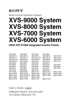 1
1 -
 2
2 -
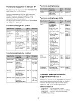 3
3 -
 4
4 -
 5
5 -
 6
6 -
 7
7 -
8
-
9
-
10
-
11
-
12
-
13
-
14
-
15
-
16
-
17
-
18
-
19
-
20
-
21
-
22
-
23
-
24
-
25
-
26
-
27
-
28
-
29
-
30
-
31
-
32
-
33
-
34
-
35
-
36
-
37
-
38
-
39
-
40
-
41
-
42
-
43
-
44
-
45
-
46
-
47
-
48
-
49
-
50
-
51
-
52
-
53
-
54
-
55
-
56
-
57
-
58
-
59
-
60
-
61
-
62
-
63
-
64
-
65
-
66
-
67
-
68
-
69
-
70
-
71
-
72
-
73
-
74
-
75
-
76
-
77
-
78
-
79
-
80
-
81
-
82
-
83
-
84
-
85
-
86
-
87
-
88
-
89
-
90
-
91
-
92
-
93
-
94
-
95
-
96
-
97
-
98
-
99
-
100
-
101
-
102
-
103
-
104
-
105
-
106
-
107
-
108
-
109
-
110
-
111
-
112
-
113
-
114
-
115
-
116
-
117
-
118
-
119
-
120
-
121
-
122
-
123
-
124
-
125
-
126
-
127
-
128
-
129
-
130
-
131
-
132
-
133
-
134
-
135
-
136
-
137
-
138
-
139
-
140
-
141
-
142
-
143
-
144
-
145
-
146
-
147
-
148
-
149
-
150
-
151
-
152
-
153
-
154
-
155
-
156
-
157
-
158
-
159
-
160
-
161
-
162
-
163
-
164
-
165
-
166
-
167
-
168
-
169
-
170
-
171
-
172
-
173
-
174
-
175
-
176
-
177
-
178
-
179
-
180
-
181
-
182
-
183
-
184
-
185
-
186
-
187
-
188
-
189
-
190
-
191
-
192
-
193
-
194
-
195
-
196
-
197
-
198
-
199
-
200
-
201
-
202
-
203
-
204
-
205
-
206
-
207
-
208
-
209
-
210
-
211
-
212
-
213
-
214
-
215
-
216
-
217
-
218
-
219
-
220
-
221
-
222
-
223
-
224
-
225
-
226
-
227
-
228
-
229
-
230
-
231
-
232
-
233
-
234
-
235
-
236
-
237
-
238
-
239
-
240
-
241
-
242
-
243
-
244
-
245
-
246
-
247
-
248
-
249
-
250
-
251
-
252
-
253
-
254
-
255
-
256
-
257
-
258
-
259
-
260
-
261
-
262
-
263
-
264
-
265
-
266
-
267
-
268
-
269
-
270
-
271
-
272
-
273
-
274
-
275
-
276
-
277
-
278
-
279
-
280
-
281
-
282
-
283
-
284
-
285
-
286
-
287
-
288
-
289
-
290
-
291
-
292
-
293
-
294
-
295
-
296
-
297
-
298
-
299
-
300
-
301
-
302
-
303
-
304
-
305
-
306
-
307
-
308
-
309
-
310
-
311
-
312
-
313
-
314
-
315
-
316
-
317
-
318
-
319
-
320
-
321
-
322
-
323
-
324
-
325
-
326
-
327
-
328
-
329
-
330
-
331
-
332
-
333
-
334
-
335
-
336
-
337
-
338
-
339
-
340
-
341
-
342
-
343
-
344
-
345
-
346
-
347
-
348
-
349
-
350
-
351
-
352
-
353
-
354
-
355
-
356
-
357
-
358
-
359
-
360
-
361
-
362
-
363
-
364
-
365
-
366
-
367
-
368
-
369
-
370
-
371
-
372
-
373
-
374
-
375
-
376
-
377
-
378
-
379
-
380
-
381
-
382
-
383
-
384
-
385
-
386
-
387
-
388
-
389
-
390
-
391
-
392
-
393
-
394
-
395
-
396
-
397
-
398
-
399
-
400
-
401
-
402
-
403
-
404
-
405
-
406
-
407
-
408
-
409
-
410
-
411
-
412
-
413
-
414
-
415
-
416
-
417
-
418
-
419
-
420
-
421
-
422
-
423
-
424
-
425
-
426
-
427
-
428
-
429
-
430
-
431
-
432
-
433
-
434
-
435
-
436
-
437
-
438
-
439
-
440
-
441
-
442
-
443
-
444
-
445
-
446
-
447
-
448
-
449
-
450
-
451
-
452
-
453
-
454
-
455
-
456
-
457
-
458
-
459
-
460
-
461
-
462
-
463
-
464
-
465
-
466
-
467
-
468
-
469
-
470
-
471
-
472
-
473
-
474
-
475
-
476
-
477
-
478
-
479
-
480
-
481
-
482
-
483
-
484
-
485
-
486
-
487
-
488
-
489
-
490
-
491
-
492
-
493
-
494
-
495
-
496
-
497
-
498
-
499
-
500
-
501
-
502
-
503
-
504
-
505
-
506
-
507
-
508
-
509
-
510
-
511
-
512
-
513
-
514
-
515
-
516
-
517
-
518
-
519
-
520
-
521
-
522
-
523
-
524
-
525
-
526
-
527
-
528
-
529
-
530
-
531
-
532
-
533
-
534
-
535
-
536
-
537
-
538
-
539
-
540
-
541
-
542
-
543
-
544
-
545
-
546
-
547
-
548
-
549
-
550
-
551
-
552
-
553
-
554
-
555
-
556
-
557
-
558
-
559
-
560
-
561
-
562
-
563
-
564
-
565
-
566
-
567
 |
 |

Multi Format Switcher System
XVS-9000 System
XVS-8000 System
XVS-7000 System
XVS-6000 System
(With ICP-X7000 Integrated Control Panel)
User’s Guide
[English]
Software Version 3.4 and Later
1st Edition (Revised 10)
XVS-9000
XVS-8000
XVS-7000
XVS-6000
XKS-S9112
XKS-S8110
XKS-S8111
XKS-S8112
XKS-T8110
XKS-Q8111
XKS-C9111
XKS-C9111N
XKS-C8111
XKS-C9121
XKS-C9121N
XKS-S9167
XKS-S8165
XKS-S8167
XKS-T8165
XKS-Q8166
XKS-C8166
XKS-8160
XKS-8210
XKS-7210
XKS-8440
XKS-8460
XKS-8470
XKS-8475
XZS-9200
XZS-9510
XZS-9520
XZS-9530
XZS-9540
XZS-9550
XZS-8200
XZS-8510
XZS-8520
XZS-8530
XZS-8540
XZS-8550
XZS-7200
XZS-7510
XZS-7520
XZS-7530
XZS-6200
XZS-6510
XZS-6520
ICP-X7000
MKS-X7075
MKS-X7011
MKS-X7017
MKS-X7018
MKS-X7019
MKS-X7020
MKS-X7021
MKS-X7023
MKS-X7024
MKS-X7026
MKS-X7031TB
MKS-X7032
MKS-X7033
MKS-X7035
MKS-X7040
MKS-X7041
MKS-X7042
MKS-X2700
MKS-X7700
MKS-X7701
MKS-X7702